Nissan Juke Service and Repair Manual : Compressor dose dot operate
Description
SYMPTOM Compressor dose not operate.
Diagnosis Procedure
NOTE
:
ÔÇó Perform self-diagnosis with CONSULT-III before performing symptom diagnosis.
If any malfunction result or
DTC is detected, perform the corresponding diagnosis.
ÔÇó Check that refrigerant is enclosed in cooler cycle normally. If the refrigerant amount is shortage from proper amount, perform the inspection of refrigerant leakage 1.CHECK A/C INDICATOR
1. Turn ignition switch ON.
2. Operate blower motor.
3. Check that A/C indicator is turned ON/OFF when operating A/C switch.
Is the inspection result normal? YES >> GO TO 2.
NO >> GO TO 5.
2.CHECK MAGNET CLUTCH OPERATION
Check magnet clutch. Refer to HAC-232, "Component Function Check".
Does it operate normally? YES >> GO TO 3.
NO >> Repair or replace malfunctioning parts.
3.CHECK REFRIGERANT PRESSURE SENSOR
Check refrigerant pressure sensor. Refer to EC-423, "Component Function Check".
Is the inspection result normal? YES >> GO TO 4.
NO >> Repair or replace malfunctioning parts.
4.CHECK BCM OUTPUT SIGNAL
 With CONSULT-III
1. Select ÔÇťDATA MONITORÔÇŁ mode of ÔÇťECMÔÇŁ using CONSULT-III.
2. Select ÔÇťAIR COND SIGÔÇŁ and ÔÇťHEATER FAN SWÔÇŁ, and check status under the following conditions.
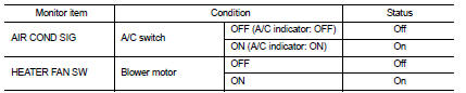
Is the inspection result normal? YES >> Replace IPDM E/R. Refer to PCS-34, "Removal and Installation" (with Intelligent Key) or PCS-63, "Removal and Installation" (without Intelligent Key).
NO >> Replace BCM. Refer to BCS-93, "Removal and Installation" (with Intelligent Key) or BCS-161, "Removal and Installation" (without Intelligent Key).
5.CHECK A/C SWITCH
Check A/C switch. Refer to HAC-220, "Component Function Check".
Is the inspection result normal? YES >> GO TO 6.
NO >> Repair or replace the malfunctioning parts.
6.CHECK BLOWER FAN ON SIGNAL
Check blower fan ON signal. Refer to HAC-222, "Component Function Check".
Is the inspection result normal? YES >> GO TO 7.
NO >> Repair or replace the malfunctioning parts 7.CHECK THERMO CONTROL AMP.
Check thermo control amp. Refer to HAC-224, "Component Function Check".
Is the inspection result normal? YES >> Replace BCM. Refer to BCS-93, "Removal and Installation" (with Intelligent Key) or BCS-161, "Removal and Installation" (without Intelligent Key).
NO >> Repair or replace the malfunctioning parts
 Insufficient heating
Description
Symptom
ÔÇó Insufficient heating
ÔÇó No warm air comes out. (Air flow volume is normal.)
Diagnosis Procedure
NOTE:
Perform self-diagnosis with CONSULT-III before performing symptom d ...

Other materials:
Radiator : Inspection
Check radiator for mud or clogging. If necessary, clean radiator as follows.
CAUTION:
ÔÇó Be careful not to bend or damage radiator fins.
ÔÇó When radiator is cleaned without removal, remove all surrounding parts such as
radiator cooling fan
assembly and horns. Then tape harness and harness ...
Front regulator
Exploded View
1. Front door panel
2. Lower sash (front)
3. Sealing screen
4. Pull handle bracket
5. Front door glass run
6. Front door glass
7. Power window motor
8. Front door regulator assembly
9. Lower sash (rear)
: Vehicle fro
Removal and Installation
REMOVAL
1. Remove the f ...
P0840 transmission fluid pressure SEN/SW A
DTC Logic
DTC DETECTION LOGIC
DTC CONFIRMATION PROCEDURE
NOTE:
If ÔÇťDTC CONFIRMATION PROCEDUREÔÇŁ has been previously performed, always turn
ignition switch
OFF and wait at least 10 seconds before performing the next test.
After the repair, perform the following procedure to confirm the ...
