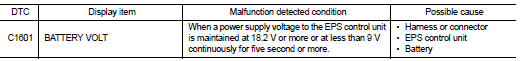
Nissan Juke Service and Repair Manual : C1601 battery power supply
DTC Logic
DTC DETECTION LOGIC
DTC CONFIRMATION PROCEDURE
1.PRECONDITIONING
If “DTC CONFIRMATION PROCEDURE” has been previously conducted, always turn ignition switch OFF and wait at least 10 seconds before conducting the next test.
>> GO TO 2.
2.DTC REPRODUCTION PROCEDURE
 With CONSULT-III
1. Turn the ignition switch OFF to ON.
2. Perform “EPS” self-diagnosis.
Is DTC “C1601” detected? YES >> Proceed to diagnosis procedure. Refer to STC-19, "Diagnosis Procedure".
NO >> INSPECTION EN
Diagnosis Procedure
1.CHECK EPS CONTROL UNIT GROUND CIRCUIT
1. Turn ignition switch OFF.
2. Disconnect EPS control unit harness connector.
3. Check continuity between EPS control unit harness connector terminal and ground.
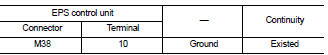
4. Connect EPS control unit harness connector.
Is the inspection result normal? YES >> GO TO 2.
NO >> Repair open circuit or short to ground or short to power in harness or connectors.
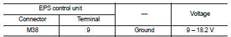
2.CHECK EPS CONTROL UNIT POWER SUPPLY CIRCUIT (1)
1. Check voltage between EPS control unit harness connector terminals and ground.
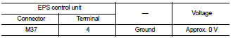
2. Turn ignition switch ON.
CAUTION:
Never start the engine
.
3. Check voltage between EPS control unit harness connector and ground.
Is the inspection result normal? YES >> GO TO 4.
NO >> GO TO 3.
3.CHECK EPS CONTROL UNIT POWER SUPPLY CIRCUIT (2)
1. Turn ignition switch OFF.
2. Check the 10A fuse (#3).
3. Check the harness for open or short between EPS control unit harness connector No.4 terminal and the 10A fuse (#3).
Is the inspection result normal? YES >> Perform the trouble diagnosis for ignition power supply circuit. Refer to PG-15, "Wiring Diagram - IGNITION POWER SUPPLY -".
NO >> Repair or replace error-detected parts.
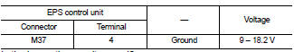
4.CHECK EPS CONTROL UNIT POWER SUPPLY CIRCUIT (3)
1. Turn ignition switch OFF.
2. Check voltage between EPS control unit harness connector terminals and ground.
3. Turn ignition switch ON.
CAUTION:
Never start the engine.
4. Check voltage between EPS control unit harness connector and ground.
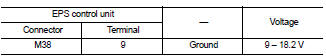
Is the inspection result normal? YES >> GO TO 6.
NO >> GO TO 5.
5.CHECK EPS CONTROL UNIT POWER SUPPLY CIRCUIT (4)
1. Turn ignition switch OFF.
2. Check the 60A fusible link (M).
3. Check the harness for open or short between EPS control unit harness connector No.9 terminal and the 60A fusible link (M).
Is the inspection result normal? YES >> Perform the trouble diagnosis for power supply circuit. Refer to PG-10, "Wiring Diagram - BATTERY POWER SUPPLY -".
NO >> Repair or replace error-detected parts.
6.CHECK TERMINALS AND HARNESS CONECTORS
Check the EPS control unit pin terminals for damage or loose connection with harness connector.
Is the inspection result normal? YES >> EPS control unit is malfunctioning. Replace steering column assembly. Refer to ST-10, "Removal and Installation".
NO >> Repair or replace error-detected parts.

 C1604 torque sensor
DTC Logic
DTC DETECTION LOGI
DTC CONFIRMATION PROCEDURE
1.PRECONDITIONING
If “DTC CONFIRMATION PROCEDURE” has been previously conducted, always turn
ignition switch OFF and
wait at least ...
Other materials:
CVT shift selector
Exploded View
1. Selector lever knob
2. Lock pin
3. Knob cover
4 Position indication panel
5. CVT shift selector assembly
6. CVT shift lock unit
7. Key interlock rod*
8. Indicator lamp
:N·m (kg-m, it-lb)
*: Without push engine starter
Removal and Installation
REMOVAL
CAUTION:
A ...
System
System Diagram
MODELS WITH USB CONNECTION FUNCTION
NOTE:
An antenna base integrated with radio antenna amp. is adopted.
MODELS WITHOUT USB CONNECTION FUNCTION
NOTE:
An antenna base integrated with radio antenna amp. is adopted.
System Description
AUDIO SYSTEM
Audio functions
AUDIO ...
Precaution Necessary for Steering Wheel Rotation after Battery Disconnect
NOTE:
• Before removing and installing any control units, first turn the ignition
switch to the LOCK position, then disconnect
both battery cables.
• After finishing work, confirm that all control unit connectors are connected
properly, then re-connect both
battery cables.
• Always us ...
