Nissan Juke Service and Repair Manual : C1111 ABS motor, motor relay system
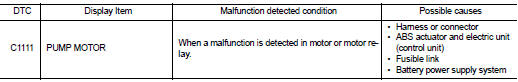
DTC Logic
DTC DETECTION LOGIC
DTC CONFIRMATION PROCEDURE
1.PRECONDITIONING
If ŌĆ£DTC CONFIRMATION PROCEDUREŌĆØ has been previously conducted, always turn ignition switch OFF and wait at least 10 seconds before conducting the next test.
>> GO TO 2.
2.CHECK DTC DETECTION
 With CONSULT-III.
1. Turn the ignition switch OFF to ON.
2. Perform self-diagnosis for ŌĆ£ABSŌĆØ.
Is DTC ŌĆ£C1111ŌĆØ detected? YES >> Proceed to BRC-163, "Diagnosis Procedure".
NO >> INSPECTION END
Diagnosis Procedure
1.CHECK CONNECTOR
1. Turn the ignition switch OFF.
2. Check ABS actuator and electric unit (control unit) harness connector for disconnection or looseness.
Is the inspection result normal? YES >> GO TO 3.
NO >> Repair or replace error-detected parts, securely lock the connector, and GO TO 2.
2.PERFORM SELF-DIAGNOSIS
Perform self-diagnosis for ŌĆ£ABSŌĆØ again.
Is DTC ŌĆ£C1111ŌĆØ detected? YES >> GO TO 3.
NO >> INSPECTION END
3.CHECK ABS MOTOR AND MOTOR RELAY POWER SUPPLY
1. Turn the ignition switch OFF.
2. Disconnect ABS actuator and electric unit (control unit) harness connector.
3. Check voltage between ABS actuator and electric unit (control unit) harness connector and ground.
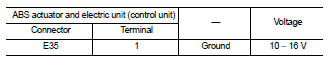
4. Turn the ignition switch ON.
CAUTION:
Never start engine.
5. Check voltage between ABS actuator and electric unit (control unit) harness connector and ground.
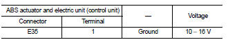
Is the inspection result normal? YES >> GO TO 5.
NO >> GO TO 4.
4.CHECK ABS MOTOR AND MOTOR RELAY POWER SUPPLY CIRCUIT
1. Turn the ignition switch OFF.
2. Check 30 A fusible link (K).
3. Check continuity and short circuit between ABS actuator and electric unit (control unit) harness connector terminal (1) and 30 A fusible link (K).
Is the inspection result normal? YES >> Perform trouble diagnosis for battery power supply. Refer to PG-10, "Wiring Diagram - BATTERY POWER SUPPLY -".
NO >> Repair or replace error-detected parts.
5.CHECK ABS ACTUATOR AND ELECTRIC UNIT (CONTROL UNIT) GROUND CIRCUIT
1. Turn the ignition switch OFF.
2. Check continuity between ABS actuator and electric unit (control unit) harness connector and the ground.
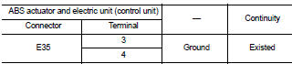
Is the inspection result normal? YES >> GO TO 6.
NO >> Repair or replace error-detected parts.
6.CHECK TERMINAL
Check ABS actuator and electric unit (control unit) pin terminals for damage or loose connection with harness connector.
Is the inspection result normal? YES >> Replace ABS actuator and electric unit (control unit). Refer to BRC-233, "Removal and Installation".
NO >> Repair or replace error-detected parts.
 C1110, C1170 ABS actuator and electric unit (control unit)
DTC Logic
DTC DETECTION LO
DTC CONFIRMATION PROCEDURE
1.PRECONDITIONING
If ŌĆ£DTC CONFIRMATION PROCEDUREŌĆØ has been previously conducted, always turn
ignition switch OFF and
wait at least 10 ...
 C1113, C1145, C1146 yaw rate/side/decel g sensor
DTC Logic
DTC DETECTION LOGIC
DTC CONFIRMATION PROCEDURE
1.PRECONDITIONING
If ŌĆ£DTC CONFIRMATION PROCEDUREŌĆØ has been previously conducted, always turn
ignition switch OFF and
wait at least ...
Other materials:
P1217 engine over temperature
DTC Logic
DTC DETECTION LOGIC
NOTE:
ŌĆó If DTC P1217 is displayed with DTC U1001, first perform the trouble diagnosis
for DTC U1001. Refer
to EC-569, "DTC Logic".
ŌĆó If DTC P1217 is displayed with DTC P0607, first perform the trouble diagnosis
for DTC P0607. Refer
to EC-685, &qu ...
Intelligent Key system (if so equipped)
WARNING
ŌĆó Radio waves could adversely affect electric medical equipment. Those who
use a pacemaker should contact the electric medical equipment manufacturer for the
possible influences before use.
ŌĆó The Intelligent Key transmits radio waves when the buttons are pushed. The FAA
advises t ...
B2602 shift position
DTC Logic
DTC DETECTION LOGIC
NOTE:
ŌĆó If DTC B2602 is displayed with DTC U1000, first perform the trouble diagnosis
for DTC U1000. Refer to
BCS-83, "DTC Logic".
ŌĆó If DTC B2602 is displayed with DTC U1010, first perform the trouble diagnosis
for DTC U1010. Refer to
BCS-84, &qu ...
