Nissan Juke Service and Repair Manual : Brake pedal
Exploded View
WITHOUT ESP
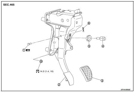
1. Clevis pin
2. Brake pedal assembly
3. Brake pedal pad
4. Stop lamp switch
5. Clip
6. Snap pin
 : Apply multi-purpose grease.
 : N·m (kg-m, ft-lb)
WITH ESP
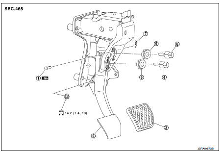
1. Clevis pin
2. Brake pedal assembly
3. Brake pedal pad
4. Brake switch/brake pedal position
switch
5. Clip
6. Stop lamp switch
7. Snap pin
 : Apply multi-purpose grease.
 : N·m (kg-m, ft-lb)
Removal and Installation
REMOVAL
1. Remove instrument lower panel. Refer to IP-13, "Removal and Installation".
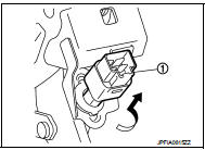
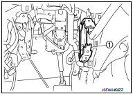
2. Disconnect the stop lamp switch and the brake switch/brake pedal position switch harness connectors.
3. Rotate the stop lamp switch and the brake switch/brake pedal position switch (1) counter clockwise to remove.
4. Disconnect the accelerator pedal harness connector and harness clip.
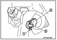
5. Remove snap pin (1) and clevis pin (2) from clevis (3) of brake booster.
6. Remove the steering member stay (1).
7. Remove the brake pedal assembly.
CAUTION:
Hold the brake booster and master cylinder assembly so as
not to drop out or contact them other parts.
8. Remove accelerator pedal from brake pedal assembly. Refer to ACC-3, "Removal and Installation".
9. Perform inspection after removal. Refer to BR-22, "Inspection and Adjustment".
INSTALLATION
Note the following, and install in the reverse order of removal.
• Apply the multi-purpose grease to the clevis pin and the mating faces. (Not necessary if grease has been already applied) NOTE
:
The clevis pin may be inserted in either direction.
• Perform adjustment after installation. Refer to BR-22, "Inspection and Adjustment".
Inspection and Adjustment
INSPECTION AFTER REMOVAL
• Check for the following items and replace the brake pedal assembly if necessary.
- Check the brake pedal upper rivet (made by aluminum) (A) for deformation.
- Check the brake pedal for bend, damage, and cracks on the welded parts.
- Check the lapping length (D) of sub-bracket (B) and slide plate (C).
D : 6.5 mm (0.256 in) or more
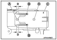
• Check clevis pin and plastic stopper (A) for damage and deformation.
If any is found, replace clevis pin.
ADJUSTMENT AFTER INSTALLATION
• Adjust each item of brake pedal after installing the brake pedal assembly to the vehicle. Refer to BR-9, "Inspection and Adjustment".
• Perform the release position learning of the accelerator pedal.
- MR16DDT: Refer to EC-134, "Work Procedure".
- HR16DE: Refer to EC-542, "Work Procedure".

 Brake piping
Front : Exploded View
WITHOUT ESP
1. Brake tube
2. ABS actuator and electric unit (control
unit)
3. Connector
4. Connector bracket
5. Master cylinder assembly
6. Brake booster
7. Lock pl ...
Other materials:
Radiator core support
HR16DE
HR16DE : Exploded View
1. Radiator core support upper
2. Air guide RH (MT models)
3. Radiator core support lower
4. Air guide LH
5. Air guide (upper)
6. Air guide LH (CVT models)
7. Air guide RH (CVT models)
: N·m (kg-m, ft-lb)
HR16DE : Removal and Installation
RADIATOR CORE ...
Compressor dose dot operate
Description
SYMPTOM
Compressor dose not operate.
Diagnosis Procedure
NOTE:
• Perform self-diagnoses with CONSULT-III before performing symptom diagnosis.
If any DTC is detected,
perform the corresponding diagnosis.
• Check that refrigerant is enclosed in cooler cycle normally. If refrig ...
CVT control system
Wiring diagram
For connector terminal arrangements, harness layouts, and alphabets in a
(option abbreviation; if not
described in wiring diagram), refer to GI-12, "Connector Information/Explanation
of Option Abbreviation".
...
