Nissan Juke Service and Repair Manual : B261A Push-button ignition switch
DTC Logic
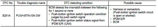
DTC DETECTION LOGIC
NOTE
:
• If DTC B261A is displayed with DTC U1000, first perform the trouble diagnosis
for DTC U1000. Refer to
BCS-83, "DTC Logic".
• If DTC B261A is displayed with DTC U1010, first perform the trouble diagnosis for DTC U1010. Refer to BCS-84, "DTC Logic".
DTC CONFIRMATION PROCEDURE
1.PERFORM DTC CONFIRMATION PROCEDURE
1. Press push-button ignition switch for 1 second under the following condition .
- Selector lever: In the P position - Brake pedal: Not depressed 2. Release push-button ignition switch and wait 1 second.
3. Check DTC in “Self diagnostic result” mode of “BCM” using CONSULT-III.
Is DTC detected? YES >> Go to SEC-106, "Diagnosis Procedure" NO >> INSPECTION END
Diagnosis Procedure
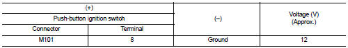
1.CHECK PUSH-BUTTON IGNITION SWITCH POWER SUPPLY CIRCUIT
1. Turn ignition switch OFF.
2. Disconnect push-button ignition switch connector.
3. Disconnect IPDM E/R connector.
4. Check voltage between push-button ignition switch harness connector and ground.
Is the inspection result normal? YES >> GO TO 2.
NO >> GO TO 3.
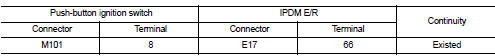
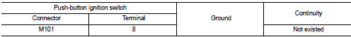
2.CHECK PUSH-BUTTON IGNITION SWITCH CIRCUIT 1
1. Check continuity between push-button ignition switch harness connector and IPDM E/R harness connector.
2. Check continuity between push-button ignition switch harness connector and ground.
Is the inspection result normal? YES >> Replace IPDM E/R. Refer to PCS-34, "Removal and Installation".
NO >> Repair harness or connector.
3.CHECK PUSH-BUTTON IGNITION SWITCH CIRCUIT 2
1. Disconnect BCM connector.
2. Check continuity between push-button ignition switch harness connector and BCM harness connector.
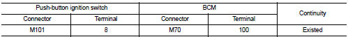
3. Check continuity between push-button ignition switch harness connector and ground.
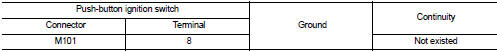
Is the inspection result normal? YES >> GO TO 4.
NO >> Repair harness or connector.
4.REPLACE BCM
1. Replace BCM. Refer to BCS-93, "Removal and Installation".
2. Perform initialization of BCM using CONSULT-III.
For initialization procedure, refer to CONSULT-III Operation Manual NATS-IVIS/NVIS.
>> INSPECTION END
 B2619 BCM
DTC Logic
DTC DETECTION LOGIC
DTC CONFIRMATION PROCEDURE
1.PERFORM DTC CONFIRMATION PROCEDURE
1. Press push-button ignition switch under the following conditions and wait
1 second or more.
- ...
 B261F ASCD clutch switch
DTC Logic
DTC DETECTION LOGIC
NOTE:
• If DTC B261F is displayed with DTC U1000, first perform the trouble diagnosis
for DTC U1000. Refer to
BCS-83, "DTC Logic".
• If DTC B261F is ...
Other materials:
Door lock status indicator does not illuminate
Diagnosis Procedure
1.CHECK DOOR LOCK STATUS INDICATOR
Check door lock status indicator.
Refer to DLK-395, "Component Function Check".
Is the inspection result normal?
YES >> GO TO 2.
NO >> Repair or replace the malfunctioning parts.
2.REPLACE BCM
1. Replace BCM ...
Unit removal and installation
Engine assembly
2WD
2WD : Exploded View
1. Washer
2. Upper torque rod (RH)
3. Engine mounting insulator (RH)
4. Rear torque rod bracket
5. Rear torque rod
6. Engine mounting insulator (LH)
7. Engine mounting frame support (LH)
8. Engine mounting bracket (LH)
: N·m (kg-m, ft-lb)
: ...
Glass
Use glass cleaner to remove smoke and dust film from the glass surfaces. It is
normal for glass to become coated with a film after the vehicle is parked in the
hot sun. Glass cleaner and a soft cloth will easily remove this film.
CAUTION
When cleaning the inside of the windows, do not use shar ...
