Nissan Juke Service and Repair Manual : B1154, B1155, B1156, B1157, B1158, B1159 diagnosis sensor unit
DTC Logic
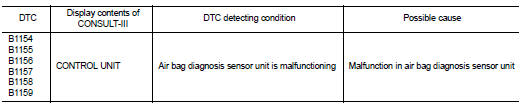
DTC DETECTION LOGIC
DTC CONFIRMATION PROCEDURE
1.CHECK SELF-DIAG RESULT
 With CONSULT-III
1. Turn ignition switch ON.
2. Perform ÔÇťSelf Diagnostic ResultÔÇŁ mode of ÔÇťAIR BAGÔÇŁ using CONSULT-III.
 Without CONSULT-III
1. Turn ignition switch ON.
2. Check the air bag warning lamp status. Refer to SRC-12, "On Board Diagnosis Function".
NOTE
:
SRS does not enter the diagnosis mode if no malfunction is detected in the user
mode.
Is malfunctioning part detected? YES >> Refer to SRC-128, "Diagnosis Procedure".
NO >> INSPECTION END
Diagnosis Procedure
WARNING:
ÔÇó Before servicing, turn ignition switch OFF, disconnect battery negative
terminal, and wait at least 3
minutes or more. (To discharge backup capacitor.)
ÔÇó Never use unspecified tester or other measuring device.
1.CHECK HARNESS CONNECTOR
Check the harness connector.
Is the inspection result normal? YES >> GO TO 2.
NO >> Replace harness connectors.
2.CHECK WIRING HARNESS
Check the wiring harness externals.
Is the inspection result normal? YES >> GO TO 3.
NO >> Replace wiring harness.
3.REPLACE AIR BAG DIAGNOSIS SENSOR UNIT
1. Replace air bag diagnosis sensor unit. Refer to SR-30, "Removal and Installation".
2. Perform DTC confirmation procedure. Refer to SRC-128, "DTC Logic".
Is DTC detected? YES >> GO TO 1.
NO >> INSPECTION END
 B1153 curtain air bag module LH
DTC Logic
DTC DETECTION LOGIC
DTC CONFIRMATION PROCEDURE
1.CHECK SELF-DIAG RESULT
With CONSULT-III
1. Turn ignition switch ON.
2. Perform ÔÇťSelf Diagnostic ResultÔÇŁ mode of ÔÇťAIR BAGÔÇŁ usi ...
 B1170, B1171, B1172, B1173, B1174, B1175 diagnosis sensor uniT
DTC Logic
DTC DETECTION LOGIC
DTC CONFIRMATION PROCEDURE
1.CHECK SELF-DIAG RESULT
With CONSULT-III
1. Turn ignition switch ON.
2. Perform ÔÇťSelf Diagnostic ResultÔÇŁ mode of ÔÇťAIR BAGÔÇŁ usi ...
Other materials:
Battery
Exploded View
1 : Battery fix frame
:N┬Ěm (kg-m, in-lb)
Removal and Installation
REMOVAL
1. Disconnect the battery cable from the negative terminal.
CAUTION:
When disconnecting, disconnect the battery cable from the negative terminal
first.
2. Remove cover of battery positive termi ...
Refilling
1. Remove filler plug (1) and gasket. Then fill oil up to mounting
hole for the filler plug.
: Vehicle front
Oil and viscosity : Refer to MA-13, "Fluids
and Lubricants".
Oil capacity : Refer to DLN-117, "General
Specifications".
CAUTION:
Carefully fill the oil. (Fill up ...
NISSAN Vehicle Immobilizer System
The NISSAN Vehicle Immobilizer System will not allow the engine to start without
the use of the registered key.
If the engine fails to start using the registered key, it may be due to interference
caused by another registered key, an automated toll road device or automated payment
device on t ...
