Nissan Juke Service and Repair Manual : Additional service when replacing transaxle assembly
Description
Perform the following work after the transaxle assembly is replaced.
CHECK LOADING OF CALIBRATION DATA
• The TCM acquires calibration data (individual characteristic value) of each solenoid that is stored in the ROM assembly (in the control valve). This enables the TCM to perform accurate control. After the TCM is replaced, check that the TCM has correctly loaded the calibration data.
G sensor calibration
• TCM stores calibration data (inherent characteristic value) of G sensor to
provide accurate control. Therefore,
it is required to perform calibration of G sensor after the following work is
performed.
Idle neutral control
• TCM corrects an individual difference in clutch clearance of the transaxle
assembly by performing the idle
neutral control learning and enables accurate idle neutral control.
• Therefore, it is required to perform idle neutral control learning after replacement or TCM.
CAUTION:
• When replacing TCM and transaxle assembly as a set, replace transaxle assembly
first and then
replace TCM.
• If the TCM is replaced in advance, perform the following items.
1. ADDITIONAL SERVICE WHEN REPLACING CONTROL VALVE OR TRANSAXLE ASSEMBLY 2. CALIBRATION OF G SENSOR 3. IDLE NEUTRAL CONTROL LEARNING
Procedure
CAUTION:
Immediately after TCM is replaced or after control valve or transaxle assembly
is replaced (after TCM
initialization is complete), self-diagnosis result of “P1701” may be displayed.
In this case, erase selfdiagnosis
result using CONSULT-III. After erasing self-diagnosis result, perform DTC P1701
reproduction
procedure and check that malfunction is not detected. Refer to TM-239, "DTC
Logic".
1.PREPARATION BEFORE WORK
 With CONSULT-III
1. Start the engine.
CAUTION:
Never drive the vehicle.
2. Select “Data monitor” in “TRANSMISSION”.
3. Select “ATFTEMP COUNT”.
Is “ATFTEMP COUNT” 47 [equivalent to 20°C (68°F)] or more? YES >> GO TO 2.
NO >> 1. Warm up the transaxle assembly until “ATFTEMP COUNT” reaches “47” [equivalent to 20°C (68°F)] or more.
2. GO TO 2.
2.PERFORM TCM INITIALIZATION
With CONSULT-III
1. Turn ignition switch OFF.
2. Turn ignition switch ON.
CAUTION:
Never start the engine.
3. Select “Self Diagnostic Results” in “TRANSMISSION”.
4. Shift selector lever to “R” position.
5. Depress slightly the accelerator pedal (Pedal angle: 2.0/8) while depressing the brake pedal.
6. Select “Erase” with step 5.
7. Release brake pedal and accelerator pedal.
8. Turn ignition switch OFF while keeping the selector lever in “R” position.
9. Wait approximately 10 seconds.
10. Turn ignition switch ON while keeping the selector lever in “R” position.
11. Select “Special function” in “TRANSMISSION”.
12. Select “CALIB DATA”.
13. Check that “CALIB DATA” value is as shown as in the following table.
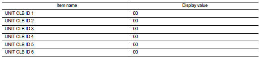
Is “CALIB DATA” value it? YES >> GO TO 3.
NO >> GO TO 1.
3.CHECK AFTER WORK
1. Shift selector lever to “P” position.
2. Check that “P” is displayed on shift position indicator on combination meter.
NOTE
:
It indicates approximately 1 or 2 seconds after shifting the selector lever to
“P” position.
Does shift position indicator display “P”? YES >> GO TO 5.
NO >> GO TO 4.
4.DETECTION OF MALFUNCTION ITEMS
Check the following items: • Harness between the TCM and the ROM assembly inside the transaxle assembly is open or shorted.
• Disconnected, loose, bent, collapsed, or otherwise abnormal connector housing
terminals
• Power supply and ground of TCM. (Refer to TM-239, "Diagnosis Procedure".)
Is the inspection result normal?
YES >> GO TO 1.
NO >> Repair or replace the malfunctioning parts.
5.PERFORM G SENSOR CALIBRATION
Refer to TM-182, "Procedure".
>> GO TO 6.
6.PERFORM IDLE NEUTRAL CONTROL LEARNING
Refer to TM-183, "Description".
>> WORK END
 Additional service when replacing TCM
Description
Always perform the following items when the TCM is replaced.
CHECK LOADING OF CALIBRATION DATA
• The TCM acquires calibration data (individual characteristic value) of each
solenoid ...
 Calibration of decel G sensor
Description
TCM stores calibration data (inherent characteristic value) of G sensor to
provide accurate control. Therefore,
it is required to perform calibration of G sensor after the following wo ...
Other materials:
Compressor
Exploded View
REMOVAL
1. High-pressure flexible hose
2. O-ring
3. Compressor
4. O-ring
5. Low-pressure flexible hose
A. To condenser
B. To evaporator
: N·m (kg-m, ft-lb)
DISASSEMBLY
1. Compressor unit
2. Field coil
3. Snap ring
4. Pulley assembly
5. Snap ring
6. Shim
7. ...
Checking engine oil level
1. Park the vehicle on a level surface and apply the parking brake.
2. Run the engine until it reaches operating temperature.
3. Turn off the engine. Wait more than 10 minutes for the oil to drain back into
the oil pan.
4. Remove the dipstick and wipe it clean.
Reinsert it all the way.
5. R ...
The braking distance is long
Description
Brake stopping distance is long when ABS function is operated.
Diagnosis Procedure
CAUTION:
Brake stopping distance on slippery road like rough road, gravel road or snowy
road may become
longer when ABS is operated than when ABS is not operated.
1.CHECK BRAKING FORCE
Check bra ...
