Nissan Juke Service and Repair Manual : Unit removal and installation
Transaxle assembly
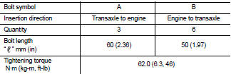
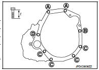
MR16DDT : Exploded View
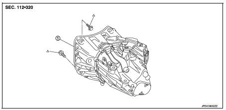
1. Transaxle assembly
 : Refer to "INSTALLATION" in
TM-84, "MR16DDT : Removal and Installation" for the locations and tightening
torque.
MR16DDT : Removal and Installation
CAUTION:
Never reuse CSC (Concentric Slave Cylinder). Because CSC slides back to the
original position every
time when removing transaxle assembly. At this timing, dust on the sliding parts
may damage a seal of
CSC and may cause clutch fluid leakage. Refer to CL-27, "Removal and
Installation".
REMOVAL
1. Disconnect battery cable from negative terminal. Refer to PG-124, "Removal and Installation".
2. Shift the shifter lever to the neutral position.
3. Remove battery. Refer to PG-124, "Removal and Installation".
4. Remove air cleaner case. Refer to EM-26, "Removal and Installation".
5. Remove air breather hose. Refer to TM-82, "MR16DDT : Removal and Installation".
6. Disconnect position switch connector. Refer to TM-77, "Removal and Installation".
7. Remove harness clip from transaxle assembly.
8. Disconnect selector cable and shifter cable from transaxle assembly. Refer to TM-78, "Removal and Installation".
9. Remove starter motor. Refer to STR-29, "MR16DDT : Removal and Installation".
10. Remove clutch tube from CSC (Concentric Slave Cylinder). Refer to CL-25, "Removal and Installation".
CAUTION:
• Keep painted surface on the body or other parts free of clutch fluid. If it
spills, wipe up immediately
and wash the affected area with water.
• Never depress clutch pedal during removal procedure.
11. Remove engine under cover.
12. Remove fender protector LH. Refer to EXT-22, "Removal and Installation".
13. Disconnect ground cable.
14. Remove front suspension member. Refer to FSU-18, "Removal and Installation".
15. Remove front drive shafts. Refer to FAX-22, "LEFT SIDE : Removal and Installation" (LEFT SIDE) and FAX-24, "RIGHT SIDE : Removal and Installation" (RIGHT SIDE).
NOTE
:
Insert a suitable plug into differential side oil seal after removing front
drive shaft.
16. Set a suitable jack to transaxle assembly and then set a suitable jack to engine assembly.
CAUTION:
When setting a suitable jack, be careful so that it does not contact with the
switch.
17. Remove engine mounting insulator (LH) mounting bolts from transaxle assembly. Refer to EM-55, "2WD : Removal and Installation".
: Vehicle front
18. Remove rear engine mounting bracket and rear torque rod. Refer to EM-55, "2WD : Removal and Installation".
19. Remove transaxle assembly mounting bolts.
20. Remove transaxle assembly from the engine.
CAUTION:
• Fix transaxle assembly to a suitable jack.
• The transaxle assembly must not interfere with the wire harnesses and clutch tube.
21. Remove CSC. Refer to CL-27, "Removal and Installation".
INSTALLATION
Note the following, and install in the reverse order of removal.
CAUTION:
• Fix transaxle assembly to a suitable jack.
• The transaxle assembly must not interfere with the wire harnesses and clutch tube.
• When installing transaxle assembly, never bring input shaft into contact with clutch cover.
• Tapping work for tapping bolts is not applied to new transaxle case. Do not perform tapping by other than screwing tapping bolts because tapping is formed by screwing tapping bolts into transaxle case.
• Tighten transaxle assembly mounting bolts to the specified torque.
The figure is the view from the engine.
MR16DDT : Inspection
INSPECTION AFTER INSTALLATION
• Check the operation of the control linkage. Refer to TM-81, "Inspection".
• Check the oil leakage and the oil level. Refer to TM-75, "Inspection".
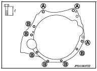
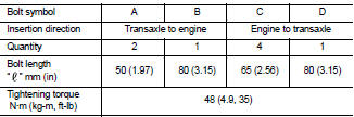
K9K : Exploded View
1. Transaxle assembly
 : Refer to "INSTALLATION" in
TM-86, "K9K : Removal and Installation" for the locations and tightening torque
K9K : Removal and Installation
CAUTION:
Never reuse CSC (Concentric Slave Cylinder). Because CSC slides back to the
original position every
time when removing transaxle assembly. At this timing, dust on the sliding parts
may damage a seal of
CSC and may cause clutch fluid leakage. Refer to CL-27, "Removal and
Installation".
REMOVAL
1. Disconnect battery cable from negative terminal. Refer to PG-124, "Removal and Installation".
2. Shift the shifter lever to the neutral position.
3. Remove battery. Refer to PG-124, "Removal and Installation".
4. Remove air cleaner case. Refer to EM-280, "Removal and Installation".
5. Remove air breather hose. Refer to TM-83, "K9K : Removal and Installation".
6. Disconnect position switch connector. Refer to TM-77, "Removal and Installation".
7. Remove harness clip from transaxle assembly.
8. Remove crankshaft position sensor. Refer to EM-288, "Removal and Installation".
9. Disconnect selector cable and shifter cable from transaxle assembly. Refer to TM-78, "Removal and Installation".
10. Remove starter motor. Refer to EM.
11. Remove clutch tube from CSC (Concentric Slave Cylinder). Refer to CL-25, "Removal and Installation".
CAUTION:
• Keep painted surface on the body or other parts free of clutch fluid. If it
spills, wipe up immediately
and wash the affected area with water.
• Never depress clutch pedal during removal procedure.
12. Remove engine under cover.
13. Remove fender protector LH. Refer to EXT-22, "Removal and Installation".
14. Disconnect ground cable.
15. Remove front drive shafts. Refer to FAX-78, "LEFT SIDE : Removal and Installation" (LEFT SIDE) and FAX-79, "RIGHT SIDE : Removal and Installation" (RIGHT SIDE).
NOTE
:
Insert a suitable plug into differential side oil seal after removing front
drive shaft.
16. Remove bracket from clutch housing.
17. Set a suitable jack to transaxle assembly and then set a suitable jack to engine assembly.
CAUTION:
When setting a suitable jack, be careful so that it does not contact with the
switch
.
18. Remove engine mounting bracket (LH) (TBD) mounting bolts from transaxle assembly. Refer to EM-326, "Removal and Installation".
 : Vehicle front
19. Remove bracket stay mounting bolts and move thermo plunger unit aside not to interfere with work. Refer to CO-72, "Removal and Installation".
20. Remove transaxle assembly mounting bolts.
21. Remove transaxle assembly from the engine.
CAUTION:
• Fix transaxle assembly to a suitable jack.
• The transaxle assembly must not interfere with the wire harnesses and clutch tube.
22. Remove CSC. Refer to CL-27, "Removal and Installation".
INSTALLATION
Note the following, and install in the reverse order of removal.
CAUTION:
• Fix transaxle assembly to a suitable jack.
• The transaxle assembly must not interfere with the wire harnesses and clutch tube.
• When installing transaxle assembly, never bring input shaft into contact with clutch cover.
• Tapping work for tapping bolts is not applied to new transaxle case. Do not perform tapping by other than screwing tapping bolts because tapping is formed by screwing tapping bolts into transaxle case.
• Tighten transaxle assembly mounting bolts to the specified torque.
The figure is the view from the engine.
K9K : Inspection
INSPECTION AFTER INSTALLATION
• Check the operation of the control linkage. Refer to TM-81, "Inspection".
• Check the oil leakage and the oil level. Refer to TM-75, "Inspection".
 Air breather hose
MR16DDT : Exploded View
1. Clip
2. Air breather hose
3. 2 way connector
MR16DDT : Removal and Installation
REMOVAL
1. Remove air cleaner case. Refer to EM-26, "Removal and Installation& ...

Other materials:
Park/neutral position (PNP) switch : Component Inspection
1.CHECK PARK/NEUTRAL POSITION (PNP) SWITCH
1. Disconnect position switch connector. Refer to TM-77, "Removal and
Installation".
2. Check continuity between position switch terminals.
Is the inspection result normal?
YES >> INSPECTION END
NO >> Replace position switch ...
P0197, P0198 EOT sensor
DTC Logic
DTC DETECTION LOGIC
DTC CONFIRMATION PROCEDURE
1.PRECONDITIONING
If DTC Confirmation Procedure has been previously conducted, always perform
the following procedure
before conducting the next test.
1. Turn ignition switch OFF and wait at least 10 seconds.
2. Turn ignition swit ...
P2263 TC system
DTC Logic
DTC DETECTION LOGIC
Diagnosis Procedure
1.CHECK VACUUM HOSES AND VACUUM GALLERY
1. Turn ignition switch OFF.
2. Check vacuum hoses and vacuum gallery for clogging, cracks
or improper connection. Refer to EC-825, "TURBOCHARGER
BOOST CONTROL : Vacuum Hose Drawing".
Is t ...
