Nissan Juke Service and Repair Manual : Rear oil seal
REAR OIL SEAL : Removal and Installation
REMOVAL
1. Remove transaxle assembly. Refer to TM-301, "Exploded View" (CVT models) or TM-84, "MR16DDT : Exploded View" (M/T models).
2. Remove clutch cover and clutch disk (M/T models). Refer to CL-29, "EXCEPT FOR K9K : Exploded View".
3. Remove drive plate (CVT models) or flywheel (M/T models). Refer to EM-103, "Exploded View".
4. Remove rear oil seal with a suitable tool.
CAUTION:
Be careful not to damage crankshaft and cylinder block.
INSTALLATION
1. Apply the liquid gasket lightly to entire outside area of new rear oil seal.
Use Genuine Liquid Gasket or equivalent.
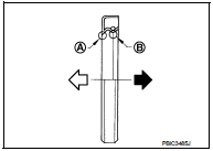
2. Install rear oil seal so that each seal lip is oriented as shown in the figure.
A : Dust seal lip
B : Oil seal lip
 : Engine outside
 : Engine inside
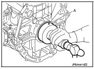
• Press-fit rear oil seal with a suitable drift (A) outer diameter 115 mm (4.53 in) and inner diameter 90 mm (3.54 in).
CAUTION:
• Be careful not to damage crankshaft and cylinder block.
• Press-fit oil seal straight to avoid causing burrs or tilting.
• Never touch grease applied onto oil seal lip.
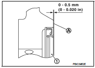
• Press in rear oil seal (1) to the position as shown in the figure.
A : Rear end surface of cylinder block
3. Install in the reverse order of removal, for the rest of parts.
 Front oil seal
FRONT OIL SEAL : Removal and Installation
REMOVAL
1. Remove the following parts.
• Front fender protector (RH): Refer to EXT-22, "Exploded View".
• Drive belt: Refer to EM-20, "Expl ...
 Cylinder head
Exploded View
REMOVAL
1. Cylinder head assembly
2. Cylinder head bolt
3. Cylinder head gasket
A. Tightening must be done following
the installation procedure.
Refer to EM-91
: N·m (kg-m, ...
Other materials:
Blower fan on signal
Component Function Check
1.CHECK BLOWER FAN ON SIGNAL
With CONSULT-III
1. Turn ignition switch ON.
2. Select “AIR CONDITIONER” of “BCM” using CONSULT-III.
3. Select “FAN ON SIG” in “DATA MONITOR” mode, and check status under the
following condition.
Is the inspection result normal?
YES &g ...
Starting system (with intelligent key)
CVT : Wiring Diagram
For connector terminal arrangements, harness layouts, and alphabets in a
(option abbreviation; if not
described in wiring diagram), refer to GI-12, "Connector Information/Explanation
of Option Abbreviation".
M/T : Wiring Diagram
For connector terminal arrangem ...
B2014 chain of STRG-IMMU
DTC Logic
DTC DETECTION LOGIC
DTC CONFIRMATION PROCEDURE
1.PERFORM DTC CONFIRMATION PROCEDURE
1. Lock steering.
NOTE:
3. Press the push-button ignition switch.
4. Check DTC in “Self Diagnostic Result” mode of “BCM” using CONSULT-III.
Is DTC detected?
YES >> Go to SEC-70, " ...
