Nissan Juke Service and Repair Manual : Cylinder head
Exploded View
REMOVAL
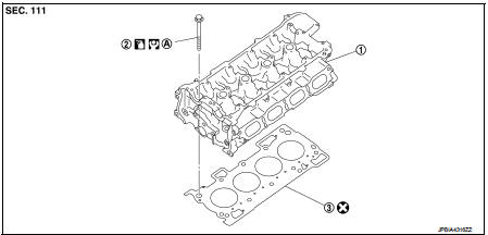
1. Cylinder head assembly
2. Cylinder head bolt
3. Cylinder head gasket
A. Tightening must be done following the installation procedure.
Refer to EM-91
 : N·m (kg-m, ft-lb)
 : Always replace after every
disassembly.
 : Should be lubricated with oil.
DISASSEMBLY
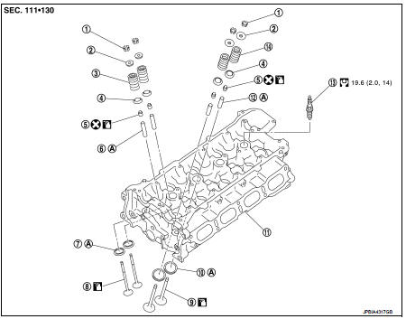
1. Valve collet
2. Valve spring retainer
3. Valve spring (EXH)
4. valve spring seat
5. Valve oil seal
6. Valve guide (EXH)
7. Valve seat (EXH)
8. Valve (EXH)
9. Valve (INT)
10. Valve seat (INT)
11. Cylinder head
12. Valve guide (INT)
13. Spark plug
14. Valve spring (INT)
A. Replacement must be following the disassembly and assembly procedure.
Refer to EM-92
: N·m (kg-m, ft-lb)
: Always replace after every
disassembly.
: Should be lubricated with oil.
Removal and Installation
REMOVAL
1. Remove the following components and related parts.
• Exhaust manifold: Refer to EM-38, "Exploded View".
• Intake manifold: Refer to EM-28, "Exploded View".
• Fuel injector and fuel tube assembly: Refer to EM-47, "Exploded View".
• Water outlet: Refer to CO-26, "Exploded View".
• Rocker cover: Refer to EM-23, "Exploded View".
• Front cover, timing chain: Refer to EM-67, "Exploded View".
• Camshaft: Refer to EM-78, "Exploded View".
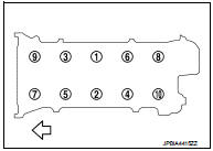
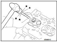
2. Remove cylinder head.
• Loosen cylinder head bolts in reverse order as shown in the figure.
 : Engine front
• Using TORX socket, loosen cylinder head bolts.
3. Remove cylinder head gasket.
INSTALLATION
1. Install cylinder head gasket.
2. Install cylinder head, and tighten cylinder head bolts in numerical order as shown in the figure with the following procedure.
: Engine front
CAUTION:
If cylinder head bolts are reused, check their outer diameters
before installation. Refer to EM-96, "Inspection".
a. Apply new engine oil to threads and seating surface of mounting bolts.
b. Tighten all cylinder head bolts.
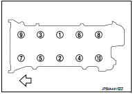
 : 40.0 N·m (4.1 kg-m, 30 ft-lb)
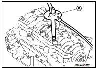
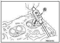
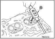
c. Turn all cylinder head bolts 100 degrees clockwise (angle tightening).
CAUTION:
Check and confirm the tightening angle by using an angle
wrench [SST: KV10112100 (BT8653-A)] (A) or protractor.
Never judge by visual inspection without the tool.
d. Completely loosen.
: 0 N·m (0 kg-m, 0 ft-lb)
CAUTION:
In this step, loosen cylinder head bolts in reverse order that
indicated in the figure.
e. Tighten all cylinder head bolts.
: 40.0 N·m (4.1 kg-m, 30 ft-lb)
f. Turn all cylinder head bolts 95 degrees clockwise (angle tightening).
g. Turn all cylinder head bolts 95 degrees clockwise again (angle tightening).
3. Install in the reverse order of removal, for the rest of parts.
Disassembly and Assembly
DISASSEMBLY
1. Remove spark plug with spark plug wrench (commercial service tool).
2. Remove valve lifter.
• Identify installation positions, and store them without mixing them up.
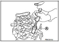
3. Remove valve collet.
• Compress valve spring with the valve spring compressor [SST: KV10116200 (J-26336-A)] (A), the attachment [SST: KV10115900 (J-26336-20)] (C), and the adapter [SST: KV10109220 ( — )] (B). Remove valve collet with a magnet hand.
CAUTION:
Be careful not to damage valve lifter holes.
4. Remove valve spring retainer and valve spring (with valve spring seat).
CAUTION:
Never remove valve spring seat from valve spring
.
5. Push valve stem to combustion chamber side, and remove valve.
• Identify installation positions, and store them without mixing them up.
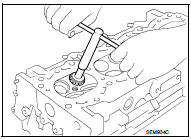
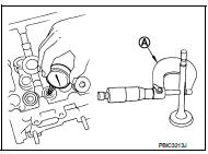
6. Remove valve oil seal with a valve oil seal puller [SST: KV10107902 (J-38959)] (A).
7. When valve seat must be replaced.
• Bore out old seat until it collapses. Boring should not continue beyond the bottom face of the seat recess in cylinder head. Set the machine depth stop to ensure this. Refer to EM-132, "Cylinder Head".
CAUTION:
Never bore excessively to prevent cylinder head from scratching.
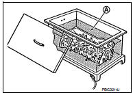
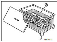
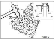
8. When valve guide must be replaced.
a. To remove valve guide, heat cylinder head to 110 to 130°C (230 to 266°F) by soaking in heated oil (A).
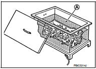
b. Drive out valve guide with a hammer and valve guide drift (commercial service tool).
CAUTION:
Cylinder head contains heat, wear protective equipment to
avoid getting burned.
ASSEMBLY
1. When valve guide is removed, install it.
CAUTION:
Replace with oversize [0.2 mm (0.008 in)] valve guide.
a. Ream cylinder head valve guide hole with a valve guide reamer (commercial service tool) (A).
For service parts: Oversize [0.2 mm (0.008 in)] Refer to EM-132, "Cylinder Head".
b. Heat cylinder head to 110 to 130°C (230 to 266°F) by soaking in heated oil (A).
c. Press valve guide (1) from camshaft side to dimensions as shown in the figure.
2 : Cylinder head
Projection (H) : Refer to EM-132, "Cylinder Head".
CAUTION:
Cylinder head contains heat, wear protective equipment to
avoid getting burned.
d. Apply reamer finish to valve guide with a valve guide reamer (commercial service tool) (A).
Standard : Refer to EM-132, "Cylinder Head".
2. When valve seat is removed, install it.
CAUTION:
Replace with oversize [0.5 mm (0.020 in)] valve seat.
a. Ream cylinder head (1) recess diameter for service valve seat (2).
For service parts: Oversize [0.5 mm (0.020 in)] Refer to EM-132, "Cylinder Head".
• Be sure to ream in circles concentric to the valve guide center.
This will enable valve seat to fit correctly.
b. Heat cylinder head to 110 to 130°C (230 to 266°F) by soaking in heated oil (A).
c. Provide valve seats cooled well with dry ice. Press-fit valve seat into cylinder head.
CAUTION:
• Never touch cold valve seats directly.
• Cylinder head contains heat, wear protective equipment to avoid getting burned.
d. Using valve seat cutter set (commercial service tool) or valve seat grinder, finish valve seat to the specified dimensions. For dimensions, refer to EM-132, "Cylinder Head".
CAUTION:
When using valve seat cutter, firmly grip the cutter handle
with both hands. Then, press on the contacting surface all
around the circumference to cut in a single drive. Improper
pressure on with the cutter or cutting many different times
may result in stage valve seat.
e. Using compound, grind to adjust valve fitting.
f. Check again for normal contact. Refer to EM-96, "Inspection".
3. Install valve oil seal.
• Install with a valve oil seal drift [SST: KV10115600 (J-38958)] (A) to match dimension in the figure.
NOTE
:
Dimension is height that measured before installing valve
spring (with valve spring seat).
Height (H) : 15.1 - 15.7 mm (0.594 - 0.618 in)
4. Install valve.
• Install larger diameter to intake side.
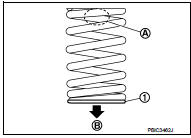
5. Install valve spring (with valve spring seat).
• Install smaller pitch (valve spring seat side) to cylinder head side (B).
1 : Valve spring seat (Do not remove from valve spring.)
• Confirm identification color (A) of valve spring.
Intake : White
Exhaust : Orange
6. Install valve spring retainer.
7. Install valve collet.
• Compress valve spring with the valve spring compressor [SST: KV10116200 (J-26336-A)] (A), the attachment [SST: KV10115900 (J-26336-20)] (C), and the adapter [SST: KV10109220 ( — )] (B). Install valve collet with a magnet hand.
CAUTION:
When working care not to damage valve lifter holes.
• Tap valve stem edge lightly with a plastic hammer after installation to check its installed condition.
8. Install valve lifter.
• Install it in the original position.
9. Install spark plug with spark plug wrench (commercial service tool).
Inspecti
INSPECTION AFTER REMOVAL
Cylinder Head Bolts Outer Diameter • Cylinder head bolts are tightened by plastic zone tightening method. Whenever the size difference between (d1) and (d2) exceeds the limit, replace them with a new one.
Limit [(d1) – (d2)]: 0.15 mm (0.0059 in)
• If reduction of outer diameter appears in a position other than (d2), use it as (d2) point.
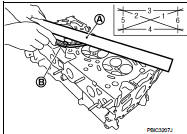
Cylinder Head Distortion NOTE
:
When performing this inspection, cylinder block distortion should be also
checked. Refer to EM-112, "Inspection".
1. Wipe off engine oil and remove water scale (like deposit), gasket, sealant, carbon, etc. with a scraper.
CAUTION:
Never allow gasket debris to enter passages for engine oil or water.
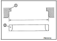
2. At each of several locations on bottom surface of cylinder head, measure the distortion in six directions using straightedge (A) and feeler gauge (B).
Limit: Refer to EM-132, "Cylinder Head".
• If it exceeds the limit, replace cylinder head.
INSPECTION AFTER DISASSEMBLY
VALVE DIMENSIONS
• Check the dimensions of each valve. For the dimensions, refer to EM-132,
"Cylinder Head".
• If dimensions are out of the standard, replace valve and check valve seat contact. Refer to “VALVE SEAT CONTACT”.
VALVE GUIDE CLEARANCE
Valve Stem Diameter
• Measure the diameter of valve stem with micrometer (A).
Standard: Refer to EM-132, "Cylinder Head".
Valve Guide Inner Diameter • Measure the inner diameter of valve guide with bore gauge.
Standard: Refer to EM-132, "Cylinder Head".
Valve Guide Clearance • (Valve guide clearance) = (Valve guide inner diameter) – (Valve stem diameter)
Standard and Limit: Refer to EM-132, "Cylinder Head".
• If the calculated value exceeds the limit, replace valve and/or valve guide. When valve guide must be replaced. Refer to EM-92, "Disassembly and Assembly".
VALVE SEAT CONTACT
• After confirming that the dimensions of valve guides and valves are within the
specifications, perform this
procedure.
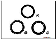
• Apply prussian blue (or white lead) onto contacting surface of valve seat to check the condition of the valve contact on the surface.
• Check if the contact area band is continuous all around the circumference.
A : OK
• If not, grind to adjust valve fitting and check again. If the contacting surface still has “NG” conditions (B) even after the recheck, replace valve seat. Refer to EM-92, "Disassembly and Assembly".
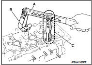
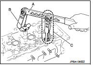
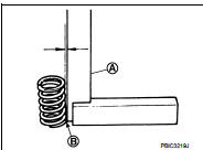
VALVE SPRING SQUAREN
• Set a try square (A) along the side of valve spring and rotate spring. Measure the maximum clearance between the top of spring and try square.
B : Contact
Limit : Refer to EM-132, "Cylinder Head".
• If it exceeds the limit, replace valve spring.
VALVE SPRING DIMENSIONS AND VALVE SPRING PRESSURE LOAD
• Check valve spring pressure with valve spring seat installed at the specified spring height.
CAUTION:
Never remove valve spring seat from valve spring.
Standard : Refer to EM-132, "Cylinder Head".
• If the installation load or load with valve open is out of the standard, replace valve spring (with valve spring seat).
INSPECTION AFTER INSTALLATION
Inspection for Leakage The following are procedures for checking fluids leakage, lubricates leakage, and exhaust gases leakage.
• Before starting engine, check oil/fluid levels including engine coolant and engine oil. If less than required quantity, fill to the specified level. Refer to MA-13, "Fluids and Lubricants".
• Use procedure below to check for fuel leakage.
- Turn ignition switch “ON” (with engine stopped). With fuel pressure applied to fuel piping, check for fuel leakage at connection points.
- Start engine. With engine speed increased, check again for fuel leakage at connection points.
• Run engine to check for unusual noise and vibration.
• Warm up engine thoroughly to check there is no leakage of fuel, exhaust gases, or any oil/fluids including engine oil and engine coolant.
• Bleed air from lines and hoses of applicable lines, such as in cooling system.
• After cooling down engine, again check oil/fluid levels including engine oil and engine coolant. Refill to the specified level, if necessary.
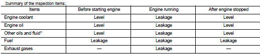
*: Transmission/transaxle/CVT fluid, power steering fluid, brake fluid, etc.
 Rear oil seal
REAR OIL SEAL : Removal and Installation
REMOVAL
1. Remove transaxle assembly. Refer to TM-301, "Exploded View" (CVT models)
or TM-84, "MR16DDT :
Exploded View" (M/T models).
...
 Oil pan (upper)
Exploded View
1. O-ring
2. Oil pan (upper)
3. Oil level gauge guide
4. O-ring
5. Oil level gauge
6. Oil pump drive chain
7. Crankshaft sprocket
8. Oil pump sprocket
9. Oil pump chain ...
Other materials:
Body side trim
Exploded View
1. Rear body side welt
2. Center pillar upper garnish
3. Front body side welt
4. Front pillar garnish
5. Metal clip
6. Dash side finisher
7. Harness clip
8. Front kicking plate inner
9. Center pillar lower garnish
10. Rear kicking plate inner
: Clip
: Pawl
: Metal ...
C1116 stop lamp switch
DTC Logic
DTC DETECTION LOGIC
DTC CONFIRMATION PROCEDURE
1.PRECONDITIONING
If “DTC CONFIRMATION PROCEDURE” has been previously conducted, always turn
ignition switch OFF and
wait at least 10 seconds before conducting the next test.
>> GO TO 2.
2.CHECK DTC DETECTION
With CONSULT ...
Air cleaner filter
Removal and Installation
REMOVAL
1. Remove air duct assembly (duct side) (1).
2. Unhook the tabs (A) of both ends of the air cleaner cover.
3. Remove the air cleaner filter (1) and air cleaner body (2) from
the air cleaner case.
4. Remove the air cleaner filter from the air cleaner body.
...
