Nissan Juke Service and Repair Manual : Blower fan on signal
Component Function Check
1.CHECK BLOWER FAN ON SIGNAL
 With CONSULT-III
1. Turn ignition switch ON.
2. Select “AIR CONDITIONER” of “BCM” using CONSULT-III.
3. Select “FAN ON SIG” in “DATA MONITOR” mode, and check status under the following condition.
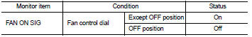
Is the inspection result normal? YES >> INSPECTION END
NO >> Refer to HAC-222, "Diagnosis Procedure".
Diagnosis Procedure
1.CHECK FAN SWITCH POWER SUPPLY SIGNAL
1. Turn ignition switch OFF.
2. Disconnect A/C control harness connector.
3. Turn ignition switch ON.
4. Check output waveform between A/C control and ground with using oscilloscope.
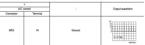
Is the inspection result normal? YES >> Replace A/C control. Refer to HAC-239, "Removal and Installation".
NO >> GO TO 2.
2.CHECK BLOWER FAN ON SIGNAL CIRCUIT FOR OPEN
1. Turn ignition switch OFF.
2. Disconnect BCM connector.
3. Check continuity A/C control harness connector and BCM harness connector.
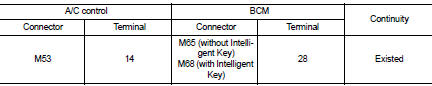
Is the inspection result normal? YES >> GO TO 3.
NO >> Repair harness or connector.
3.CHECK BLOWER FAN ON SIGNAL CIRCUIT FOR SHORT
Check continuity between A/C control harness connector and ground.
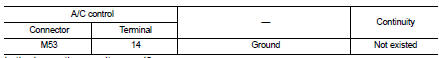
Is the inspection result normal? YES >> Replace BCM. Refer to BCS-93, "Removal and Installation" (with Intelligent Key) or BCS-161, "Removal and Installation" (without Intelligent Key).
NO >> Repair harness or connector.
 A/C switch
Component Function Check
1.CHECK A/C ON SIGNAL
With CONSULT-III
1. Turn ignition switch ON.
2. Select “AIR CONDITIONER” of “BCM” using CONSULT-III.
3. Select “AIR COND SW” in “DATA MONITOR” mode, ...
 Thermo control amplifier
Component Function Check
1.CHECK A/C ON SIGNAL
With CONSULT-III
1. Turn ignition switch ON.
2. Select “AIR CONDITIONER” of “BCM” using CONSULT-III.
3. Select “THERMO AMP” in “DATA MONITOR” mode, ...
Other materials:
U1010 control unit (can)
Description
CAN (Controller Area Network) is a serial communication line for real time
application. It is an on-vehicle multiplex
communication line with high data communication speed and excellent error
detection ability. Many electronic
control units are equipped onto a vehicle, and each co ...
Fuel filter
Exploded View
Removal and Installation
REMOVAL (RHD)
1. Remove quick connectors in the following procedures.
• Pinch quick connector square-parts with your fingers, and pull
out the quick connector by hand.
• If quick connector and tube on vehicle are stuck, push and pull
several times ...
License plate lamp circuit
Without daytime running light system
WITHOUT DAYTIME RUNNING LIGHT SYSTEM : Component Function Check
1.CHECK TAIL LAMP (RH) OPERATION
Check that the tail lamp (RH) is turned ON.
Is the inspection result normal?
YES >> GO TO 2.
NO >> Check tail lamp circuit. Refer to EXL-61, &qu ...
