Nissan Juke Service and Repair Manual : B2014 chain of STRG-IMMU
DTC Logic
DTC DETECTION LOGIC
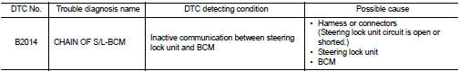
DTC CONFIRMATION PROCEDURE
1.PERFORM DTC CONFIRMATION PROCEDURE
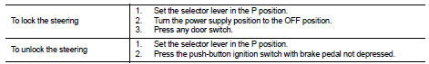
1. Lock steering.
NOTE
:
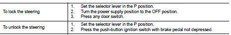
3. Press the push-button ignition switch.
4. Check DTC in “Self Diagnostic Result” mode of “BCM” using CONSULT-III.
Is DTC detected? YES >> Go to SEC-70, "Diagnosis Procedure".
NO >> INSPECTION END
Diagnosis Procedure
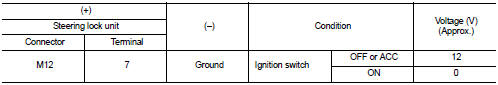
1.CHECK STEERING LOCK UNIT POWER SUPPLY
1. Turn ignition switch OFF.
2. Disconnect steering lock unit connector.
3. Check voltage between steering lock unit harness connector and ground.
Is the inspection result normal? YES >> GO TO 3.
NO >> GO TO 2.
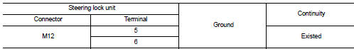
2.CHECK STEERING LOCK UNIT POWER SUPPLY CIRCUIT
1. Disconnect BCM connector.
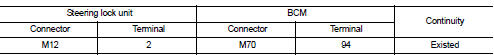
2. Check continuity between steering lock unit harness connector and BCM harness connector.
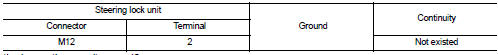
3. Check continuity between steering lock unit harness connector and ground.
Is the inspection result normal? YES >> GO TO 7.
NO >> Repair or replace harness.
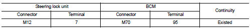
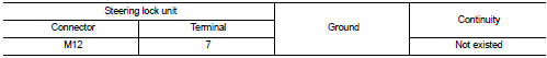
3.CHECK STEERING LOCK UNIT GROUND CIRCUIT
Check continuity between steering lock unit and ground.
Is the inspection result normal? YES >> GO TO 4.
NO >> Repair or replace harness.
4.CHECK STEERING LOCK UNIT COMMUNICATION SIGNAL
1. Connect steering lock unit connector and BCM connector.
2. Read voltage signal between steering lock unit harness connector and ground.
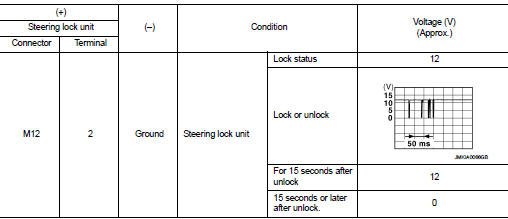
NOTE:
Is the inspection result normal? YES >> GO TO 5.
NO >> GO TO 6.
5.REPLACE STEERING LOCK UNIT
1. Replace steering lock unit.
2. Perform the service procedure for steering lock unit replacement. Refer to CONSULT-III Operation Manual NATS-IVIS/NVIS.
>> INSPECTION END
6.CHECK STEERING LOCK UNIT COMMUNICATION CIRCUIT
1. Disconnect steering lock unit and BCM connector.
2. Check continuity between steering lock unit harness connector and BCM harness connector.
3. Check continuity between steering lock unit harness connector and ground.
Is the inspection result normal? YES >> GO TO 7.
NO >> Repair or replace harness.
7.REPLACE BCM
1. Replace BCM. Refer to BCS-93, "Removal and Installation".
2. Perform initialization of BCM and registration of all Intelligent Keys using CONSULT-III.
For initialization and registration procedures, refer to CONSULT-III Operation Manual NATS-IVIS/NVIS.
>> INSPECTION END
 B2013 steering lock unit
DTC Logic
DTC DETECTION LOGIC
DTC CONFIRMATION PROCEDURE
1.PERFORM DTC CONFIRMATION PROCEDURE
1. Lock the steering.
NOTE:
3. Press the push-button ignition switch.
4. Check DTC in “Self D ...
 B2555 stop lamp
DTC Logic
DTC DETECTION LOGIC
DTC CONFIRMATION PROCEDURE
1.PERFORM DTC CONFIRMATION PROCEDURE
1. Depress the brake pedal and wait 1 second or more.
2. Check DTC in “Self Diagnostic Result” mode ...
Other materials:
LAN System can system (type 11)
DTC/CIRCUIT DIAGNOSIS
Main line between IPDM-E and DLC circuit
Diagnosis Procedure
1.CHECK CONNECTOR
1. Turn the ignition switch OFF.
2. Disconnect the battery cable from the negative terminal.
3. Check the following terminals and connectors for damage, bend and loose
connection (connector s ...
Wiring diagram
HORN
Wiring Diagram
For connector terminal arrangements, harness layouts, and alphabets in a
(option abbreviation; if not
described in wiring diagram), refer to GI-12, "Connector Information/Explanation
of Option Abbreviation".
...
Back door finisher
Exploded View
1. Rear view camera
2. Back door opener request switch
3. Emblem
4. Back door finisher
: Clip
: Pawl
: Do not reuse
Removal and Installation
REMOVAL
1. Remove back door trim. Refer to INT-35, "BACK DOOR LOWER FINISHER :
Removal and Installation".
2. Remove ba ...
