Nissan Juke Service and Repair Manual : Power generation voltage variable control system operation inspection
Inspection Procedure
CAUTION:
When performing this inspection, always use a charged battery that has completed
the battery inspection.
(When the charging rate of the battery is low, the response speed of the voltage change will become slow. This can cause an incorrect inspection.)
1.CHECK ECM (CONSULT-III)
Perform ECM self-diagnosis with CONSULT-III. Refer to EC-501, "CONSULT-III Function" (MR16DDT), or EC-835, "CONSULT-III Function" (K9K).
Self-diagnostic results content No malfunction detected>> GO TO 2.
Malfunction detected>> Check applicable parts, and repair or replace corresponding parts.
2.CHECK OPERATION OF POWER GENERATION VOLTAGE VARIABLE CONTROL SYSTEM
1. Connect CONSULT-III and start the engine.
2. Check that the selector lever is in “P” or “N” position and that all of the electric loads and A/C, etc. are turned OFF.
3. Select “ALTERNATOR DUTY” at “Active Test” of “ENGINE”, and then check the value of “BATTERY VOLT” monitor when DUTY value of “ALTERNATOR DUTY” is set to 40.0 %.
“BATTERY VOLT”
2 seconds after setting the
DUTY value of “ALTERNATOR
DUTY” to 40.0 %
: 12 - 13.6 V
4. Check the value of “BATTERY VOLT” monitor when DUTY value of “ALTERNATOR DUTY” is set to 80.0%.
“BATTERY VOLT”
20 seconds after setting
the DUTY value of “ALTERNATOR
DUTY” to 80.0 %
: +0.5 V or more against
the value of “BATTERY
VOLT” monitor when
DUTY value is 40.0 %
Is the measurement value within the specification? YES >> INSPECTION END
NO >> GO TO 3.
3.CHECK IPDM E/R (CONSULT-III)
Perform IPDM E/R self-diagnosis with CONSULT-III. Refer to PCS-14, "CONSULT-III Function (IPDM E/R)" (with Intelligent Key system), PCS-45, "CONSULT-III Function (IPDM E/R)" (without Intelligent Key system).
Self-diagnostic results content
No malfunction detected>> GO TO 4.
Malfunction detected>> Check applicable parts, and repair or replace corresponding parts.
4.CHECK HARNESS BETWEEN ALTERNATOR AND IPDM E/R
1. Turn ignition switch OFF.
2. Disconnect alternator connector and IPDM E/R connector.
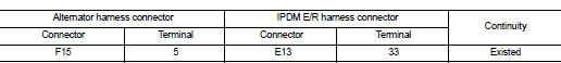
3. Check continuity between alternator harness connector and IPDM E/R harness connector.
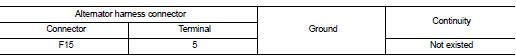
4. Check continuity between alternator harness connector and ground.
Is the inspection result normal? YES >> Replace IPDM E/R.
NO >> Repair harness or connector between IPDM E/R and alternator.
 Charging system preliminary inspection
Inspection Procedure
1.CHECK BATTERY TERMINALS CONNECTION
Check if battery terminals are clean and tight.
Is the inspection result normal?
YES >> GO TO 2.
NO >> Repair battery ter ...

Other materials:
Replacement operations
Description
• This section is prepared for technicians who have attained a high level of
skill and experience in repairing
collision-damaged vehicles and also use modern service tools and equipment.
Persons unfamiliar with body
repair techniques should not attempt to repair collision-damaged ...
Electric foldable door mirror does not operate
Diagnosis Procedure
1.CHECK DOOR MIRROR (OPEN/CLOSE MOTOR) CIRCUIT
Check door mirror (open/close motor) circuit.
Refer to MIR-25, "Component Function Check".
Is the inspection result normal?
YES >> GO TO 2.
NO >> Repair or replace the malfunctioning parts.
2.CONF ...
Door lock actuator
Driver side
DRIVER SIDE : Component Function Check
1.CHECK FUNCTION
1. Select “DOOR LOCK” of “BCM” using CONSULT-III.
2. Select “DOOR LOCK” in “ACTIVE TEST” mode.
3. Check that the function operates normally according to the following
conditions.
Is the inspection result normal?
YES >& ...
