Nissan Juke Service and Repair Manual : Door lock actuator
Driver side
DRIVER SIDE : Component Function Check
1.CHECK FUNCTION
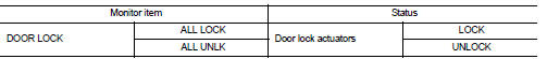
1. Select “DOOR LOCK” of “BCM” using CONSULT-III.
2. Select “DOOR LOCK” in “ACTIVE TEST” mode.
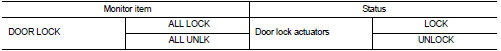
3. Check that the function operates normally according to the following conditions.
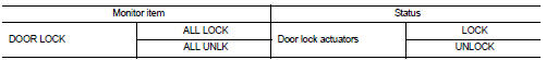
Is the inspection result normal? YES >> Door lock actuator is OK.
NO >> Refer to DLK-386, "DRIVER SIDE : Diagnosis Procedure".
DRIVER SIDE : Diagnosis Procedure
1.CHECK DOOR LOCK ACTUATOR INPUT SIGNAL
1. Turn ignition switch OFF.
2. Disconnect front door lock assembly (driver side) connector.
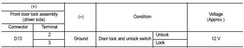
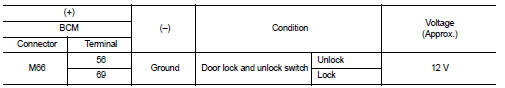
3. Check voltage between front door lock assembly (driver side) harness connector and ground.
Is the inspection result normal? YES >> Replace front door lock assembly (driver side).
NO >> GO TO 2.
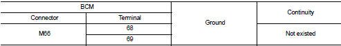
2.CHECK DOOR LOCK ACTUATOR CIRCUIT
1. Disconnect BCM connector and all door lock assembly connector.
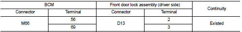
2. Check continuity between BCM harness connector and front door lock assembly (driver side) harness connector
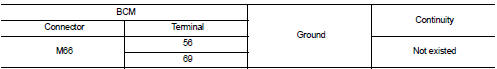
3. Check continuity between BCM harness connector and ground.
Is the inspection result normal? YES >> GO TO 3.
NO >> Repair or replace harness.
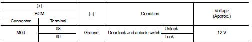
3.CHECK BCM OUTPUT SIGNAL
1. Connect BCM connector.
2. Check voltage between BCM harness connector and ground.
Is the inspection result normal? YES >> Check for internal short of each door lock actuator.
NO >> Replace BCM. Refer to BCS-161, "Removal and Installation".
Passenger side
PASSENGER SIDE : Component Function Check
1.CHECK FUNCTION
1. Select “DOOR LOCK” of “BCM” using CONSULT-III.
2. Select “DOOR LOCK” in “ACTIVE TEST” mode.
3. Check that the function operates normally according to the following conditions.
Is the inspection result normal? YES >> Door lock actuator is OK.
NO >> Refer to DLK-386, "DRIVER SIDE : Diagnosis Procedure".
PASSENGER SIDE : Diagnosis Procedure
1.CHECK DOOR LOCK ACTUATOR INPUT SIGNAL
1. Turn ignition switch OFF.
2. Disconnect front door lock assembly (passenger side) connector.
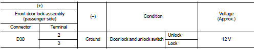
3. Check voltage between front door lock assembly (passenger side) harness connector and ground.
Is the inspection result normal? YES >> Replace front door lock assembly (passenger side).
NO >> GO TO 2.
2.CHECK DOOR LOCK ACTUATOR CIRCUIT
1. Disconnect BCM connector and all door lock assembly connector.
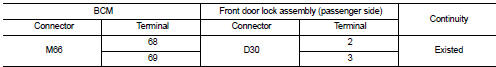
2. Check continuity between BCM harness connector and front door lock assembly (passenger side) harness connector.
3. Check continuity between BCM harness connector and ground.
Is the inspection result normal? YES >> GO TO 3.
NO >> Repair or replace harness.
3.CHECK BCM OUTPUT SIGNAL
1. Connect BCM connector.
2. Check voltage between BCM harness connector and ground.
Is the inspection result normal? YES >> Check for internal short of each door lock actuator.
NO >> Replace BCM. Refer to BCS-161, "Removal and Installation".
Rear LH
REAR LH : Component Function Check
1.CHECK FUNCTION
1. Select “DOOR LOCK” of “BCM” using CONSULT-III.
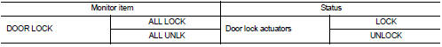
2. Select “DOOR LOCK” in “ACTIVE TEST” mode.
3. Check that the function operates normally according to the following conditions.
Is the inspection result normal? YES >> Door lock actuator is OK.
NO >> Refer to DLK-386, "DRIVER SIDE : Diagnosis Procedure".
REAR LH : Diagnosis Procedure
1.CHECK DOOR LOCK ACTUATOR INPUT SIGNAL
1. Turn ignition switch OFF.
2. Disconnect rear door lock assembly LH connector.
3. Check voltage between rear door lock assembly LH harness connector and ground.
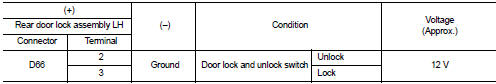
Is the inspection result normal? YES >> Replace rear door lock assembly LH.
NO >> GO TO 2.
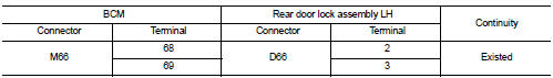
2.CHECK DOOR LOCK ACTUATOR CIRCUIT
1. Disconnect BCM connector and all door lock assembly connector.
2. Check continuity between BCM harness connector and rear door lock assembly LH harness connecto
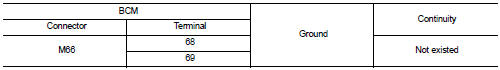
3. Check continuity between BCM harness connector and ground.
Is the inspection result normal? YES >> GO TO 3.
NO >> Repair or replace harness.
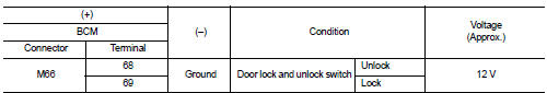
3.CHECK BCM OUTPUT SIGNAL
1. Connect BCM connector.
2. Check voltage between BCM harness connector and ground.
Is the inspection result normal? YES >> Check for internal short of each door lock actuator.
NO >> Replace BCM. Refer to BCS-161, "Removal and Installation".
Rear RH
REAR RH : Component Function Check
1.CHECK FUNCTION
1. Select “DOOR LOCK” of “BCM” using CONSULT-III.
2. Select “DOOR LOCK” in “ACTIVE TEST” mode.
3. Check that the function operates normally according to the following conditions.
Is the inspection result normal? YES >> Door lock actuator is OK.
NO >> Refer to DLK-386, "DRIVER SIDE : Diagnosis Procedure".
REAR RH : Diagnosis Procedure
1.CHECK DOOR LOCK ACTUATOR INPUT SIGNAL
1. Turn ignition switch OFF.
2. Disconnect rear door lock assembly RH connector.
3. Check voltage between rear door lock assembly RH harness connector and ground.
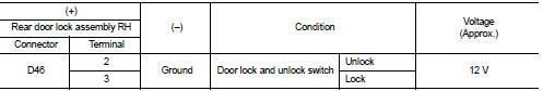
Is the inspection result normal? YES >> Replace rear door lock assembly RH.
NO >> GO TO 2.
2.CHECK DOOR LOCK ACTUATOR CIRCUIT
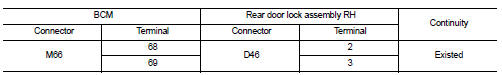
1. Disconnect BCM connector and all door lock assembly connector.
2. Check continuity between BCM harness connector and rear door lock assembly RH harness connector.
3. Check continuity between BCM harness connector and ground.
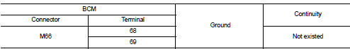
Is the inspection result normal? YES >> GO TO 3.
NO >> Repair or replace harness.
3.CHECK BCM OUTPUT SIGNAL
1. Connect BCM connector.
2. Check voltage between BCM harness connector and ground.
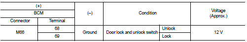
Is the inspection result normal? YES >> Check for internal short of each door lock actuator.
NO >> Replace BCM. Refer to BCS-161, "Removal and Installation".
 Back door opener switch
Component Function Check
1.CHECK FUNCTION
1. Select “TRUNK” of “BCM” using CONSULT-III.
2. Select “TRNK OPNR SW” in “DATA MONITOR” mode.
3. Check that the function operates normally according to t ...
 Door lock and unlock switch
Driver side
DRIVER SIDE : Component Function Check
1.CHECK FUNCTION
1. Select “DOOR LOCK” of “BCM” using CONSULT-III.
2. Select “CDL LOCK SW”, “CDL UNLOCK SW” in “DATA MONITOR” mode.
3. Check tha ...
Other materials:
P0171 fuel injection system function
DTC Logic
DTC DETECTION LOGIC
With the Air/Fuel Mixture Ratio Self-Learning Control, the actual mixture
ratio can be brought closely to the
theoretical mixture ratio based on the mixture ratio feedback signal from the
A/F sensor 1. The ECM calculates
the necessary compensation to correct the ...
Basic inspection
Diagnosis and repair work flow
Work Flow
DETAILED FLOW
1.INTERVIEW FROM THE CUSTOMER
Clarify customer complaints before inspection. First of all, perform an
interview utilizing BRC-34, "Diagnostic
Work Sheet" and reproduce the symptom as well as fully understand it. Ask
customer a ...
P1226 TP sensor
DTC Logic
DTC DETECTION LOGIC
DTC CONFIRMATION PROCEDURE
1.PRECONDITIONING
If DTC Confirmation Procedure has been previously conducted, always perform
the following procedure
before conducting the next test.
1. Turn ignition switch OFF and wait at least 10 seconds.
2. Turn ignition swit ...
