Nissan Juke Service and Repair Manual : Door lock and unlock switch
Driver side
DRIVER SIDE : Component Function Check
1.CHECK FUNCTION
1. Select “DOOR LOCK” of “BCM” using CONSULT-III.
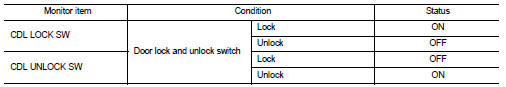
2. Select “CDL LOCK SW”, “CDL UNLOCK SW” in “DATA MONITOR” mode.
3. Check that the function operates normally according to the following conditions.
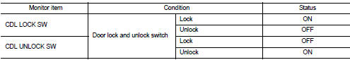
Is the inspection result normal? YES >> Door lock and unlock switch is OK.
NO >> Refer to DLK-391, "DRIVER SIDE : Diagnosis Procedure".
DRIVER SIDE : Diagnosis Procedure
1.CHECK DOOR LOCK AND UNLOCK SWITCH INPUT SIGNAL
1. Turn ignition switch OFF.
2. Disconnect power window main switch connector.
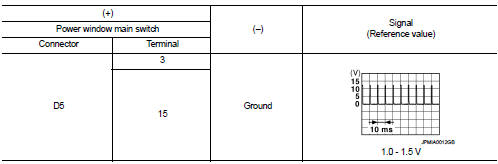
3. Check signal between power window main switch harness connector and ground using oscilloscope.
Is the inspection result normal? YES >> GO TO 3.
NO >> GO TO 2.
2.CHECK DOOR LOCK AND UNLOCK SWITCH CIRCUIT
1. Disconnect BCM connector and front power window switch (passenger side) connector.
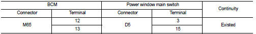
2. Check continuity between BCM harness connector and power window main switch harness connector.
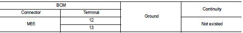
3. Check continuity between BCM harness connector and ground.
Is the inspection result normal? YES >> Replace BCM. Refer to BCS-93, "Removal and Installation".
NO >> Repair or replace harness.
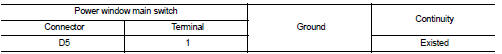
3.CHECK DOOR LOCK AND UNLOCK SWITCH GROUND
Check continuity between power window main switch harness connector and ground.
Is the inspection result normal? YES >> GO TO 4.
NO >> Repair or replace harness.
4.CHECK DOOR LOCK AND UNLOCK SWITCH
Refer to DLK-392, "DRIVER SIDE : Component Inspection".
Is the inspection result normal? YES >> GO TO 5.
NO >> Replace power window main switch. Refer to PWC-44, "Removal and Installation".
5.CHECK INTERMITTENT INCIDENT
Refer to GI-42, "Intermittent Incident".
>> INSPECTION END
DRIVER SIDE : Component Inspection
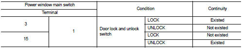
1.CHECK DOOR LOCK AND UNLOCK SWITCH
1. Turn ignition switch OFF.
2. Disconnect power window main switch connector.
3. Check continuity between power window main switch terminals.
Is the inspection result normal? YES >> INSPECTION END
NO >> Replace power window main switch.
Passenger side
PASSENGER SIDE : Component Function Check
1.CHECK FUNCTION
1. Select “DOOR LOCK” of “BCM” using CONSULT-III.
2. Select “CDL LOCK SW”, “CDL UNLOCK SW” in “DATA MONITOR” mode.
3. Check that the function operates normally according to the following conditions.
Is the inspection result normal? YES >> Door lock and unlock switch is OK.
NO >> Refer to DLK-393, "PASSENGER SIDE : Diagnosis Procedure".
PASSENGER SIDE : Diagnosis Procedure
1.CHECK DOOR LOCK AND UNLOCK SWITCH INPUT SIGNAL
1. Turn ignition switch OFF.
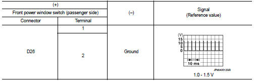
2. Disconnect front power window switch (passenger side) connector.
3. Check signal between front power window switch (passenger side) harness connector and ground using oscilloscope.
Is the inspection result normal? YES >> GO TO 3.
NO >> GO TO 2.
2.CHECK DOOR LOCK AND UNLOCK SWITCH CIRCUIT
1. Disconnect BCM connector and power window main switch connector.
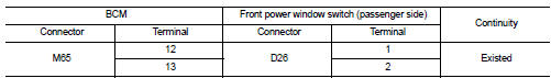
2. Check continuity between BCM harness connector and front power window switch (passenger side) harness connector.
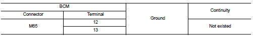
3. Check continuity between BCM harness connector and ground.
Is the inspection result normal? YES >> Replace BCM. Refer to BCS-161, "Removal and Installation".
NO >> Repair or replace harness.
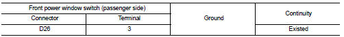
3.CHECK DOOR LOCK AND UNLOCK SWITCH GROUND
Check continuity between front power window switch (passenger side) harness connector and ground.
Is the inspection result normal? YES >> GO TO 4.
NO >> Repair or replace harness.
4.CHECK DOOR LOCK AND UNLOCK SWITCH
Refer to DLK-394, "PASSENGER SIDE : Component Inspection".
Is the inspection result normal? YES >> GO TO 5.
NO >> Replace front power window switch (passenger side). Refer to PWC-44, "Removal and Installation".
5.CHECK INTERMITTENT INCIDENT
Refer to GI-42, "Intermittent Incident".
>> INSPECTION END
Passenger side : Component Inspection
1.CHECK DOOR LOCK AND UNLOCK SWITCH
1. Turn ignition switch OFF.
2. Disconnect front power window switch (passenger side) connector.
3. Check continuity between front power window switch (passenger side) terminals.
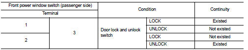
Is the inspection result normal? YES >> INSPECTION END
NO >> Replace front power window switch (passenger side).
 Door lock actuator
Driver side
DRIVER SIDE : Component Function Check
1.CHECK FUNCTION
1. Select “DOOR LOCK” of “BCM” using CONSULT-III.
2. Select “DOOR LOCK” in “ACTIVE TEST” mode.
3. Check that the function opera ...
 Door lock status indicator
Component Function Check
1.CHECK FUNCTION
1. Select “DOOR LOCK” of “BCM” using CONSULT-III.
2. Select “DOOR LOCK IND” in “ACTIVE TEST” mode.
3. Check that the function operates normally according ...
Other materials:
Trip computer
The switch for the trip computer is located on the meter panel.
When the ignition switch is placed in the ON position, modes of the trip computer
can be selected by pushing the trip computer mode switchA .
Each time the trip computer mode switchA is pushed, the display will change as
follows ...
P0740 torque converter
DTC Logic
DTC DETECTION LOGIC
DTC CONFIRMATION PROCEDURE
CAUTION:
Be careful of the driving speed.
1.PREPARATION BEFORE OPERATION (PART 1)
If another "DTC CONFIRMATION PROCEDURE" occurs just before, turn ignition
switch OFF and wait for at
least 10 seconds, then perform the next ...
Side oil seal
Removal and Installation
REMOVAL
1. Remove front drive shafts. Refer to FAX-53, "Removal and Installation".
2. Remove differential side oil seals (1) from clutch housing and
transaxle case, using an oil seal remover.
CAUTION:
Never damage transaxle case and clutch housing.
INSTA ...
