Nissan Juke Service and Repair Manual : Replacement operations
Description
• This section is prepared for technicians who have attained a high level of skill and experience in repairing collision-damaged vehicles and also use modern service tools and equipment. Persons unfamiliar with body repair techniques should not attempt to repair collision-damaged vehicles by using this section.
• Technicians are also encouraged to read the Body Repair Manual (Fundamentals) in order to ensure that the original functions and quality of the vehicle are maintained. The Body Repair Manual (Fundamentals) contains additional information, including cautions and warnings, that are not including in this manual. Technicians should refer to both manuals to ensure proper repair.
• Please note that this information is prepared for worldwide usage, and as such, certain procedures might not apply in some regions or countries.
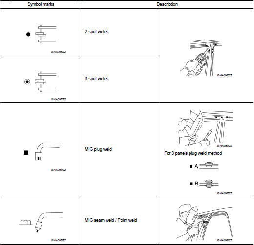
The symbols used in this section for welding operations are shown below.
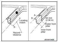
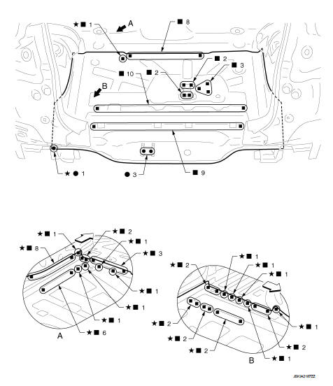
• Front pillar butt joint can be determined anywhere within shaded area as shown in the figure. The best location for the butt joint is at position A due to the construction of the vehicle.
• Determine cutting position and record distance from the locating indent. Use this distance when cutting the service part. Cut outer front pillar over 60 mm (2.36 in) above the inner front pillar cut position.
• Prepare a cutting jig to make outer pillar easier to cut. Also, this will permit the service part to be accurately cut at the joint position.
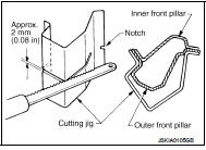
• An example of cutting operation using a cutting jig is as per the following.
1. Mark cutting lines.
A: Cut position of outer pillar B: Cut position of inner pillar 2. Align cutting line with notch on jig. Clamp jig to pillar.
3. Cut outer pillar along groove of jig (at position A).
4. Remove jig and cut remaining portions.
5. Cut inner pillar at position B in same manner.
Radiator Core Support
 Vehicle front
Replacement parts
● Side radiator core support (LH Upper)
● Side radiator core support (LH
Lower)
● Hoodledge connector (LH)
Hoodledge (RHD Models)
Work after radiator core support is removed.
Vehicle front
Replacement parts
● Front strut housing (LH)
● Hoodledge reinforcement (LH)
View B: Before installing hoodledge reinforcement
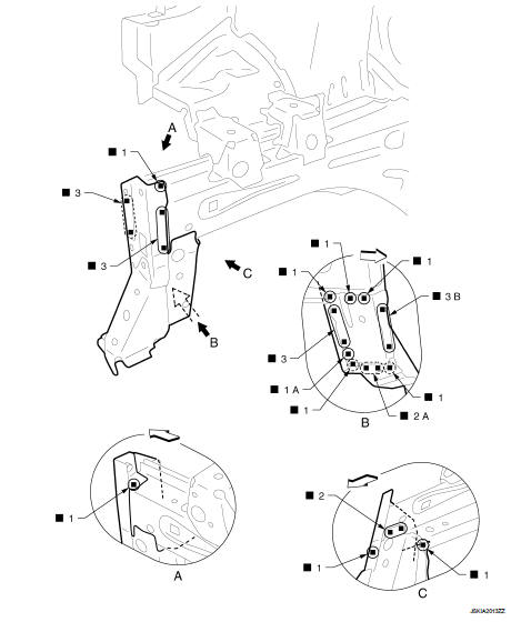
Hoodledge (LHD Models)
Work after radiator core support is removed
Vehicle front
Replacement parts ● Front strut housing (LH) ● Hoodledge reinforcement (LH)
View B: Before installing hoodledge reinforcement
Hoodledge (RHD Models Partial Replacement)
Work after radiator core support is removed.
Remove the welding points ″f″ for easier installation.
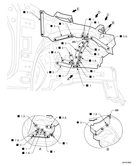
Vehicle front
Replacement parts
● Upper hoodledge (RH)
● Lower front hoodledge (RH)
● Hoodledge reinforcement (RH)
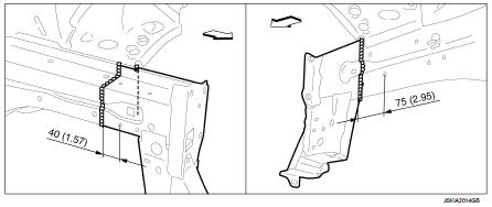
View B: Before installing hoodledge reinforcement
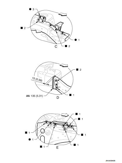
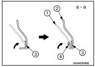
Unit: mm (in)
: Vehicle front
View D: Before installing hoodledge reinforcement
Hoodledge (LHD Models Partial Replacement)
Work after radiator core support is removed.
Remove the welding points ″f″ for easier installation.
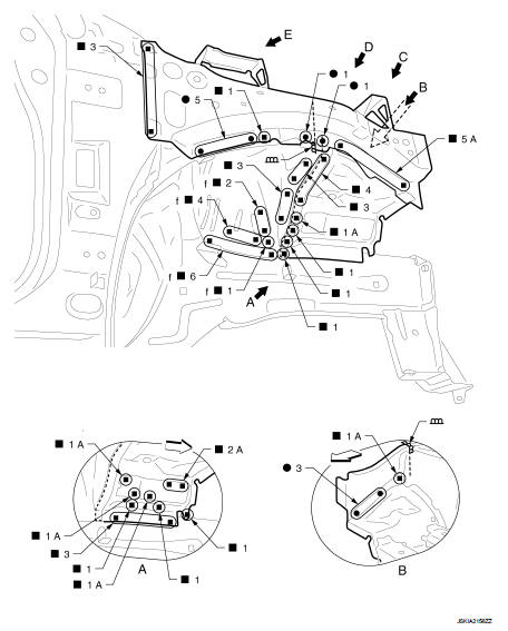
Vehicle front
Replacement parts
● Upper hoodledge (RH)
● Lower front hoodledge (RH)
● Hoodledge reinforcement (RH)
View B: Before installing hoodledge reinforcement
Unit: mm (in)
: Vehicle front
View D: Before installing hoodledge reinforcement
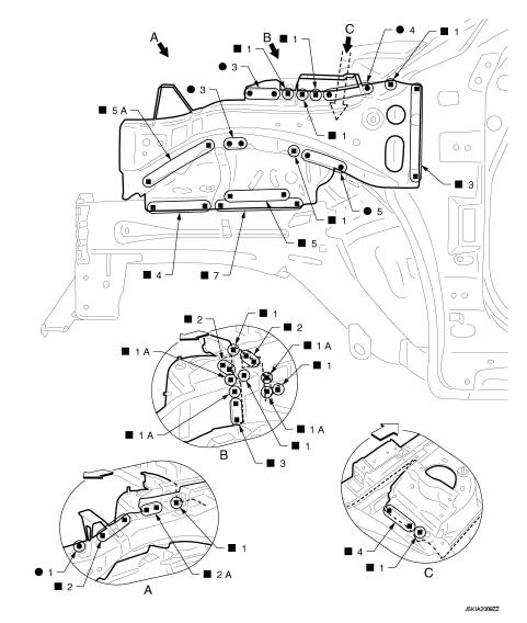
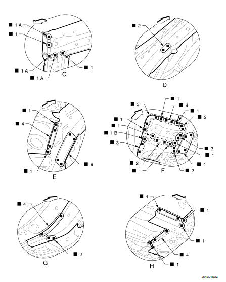
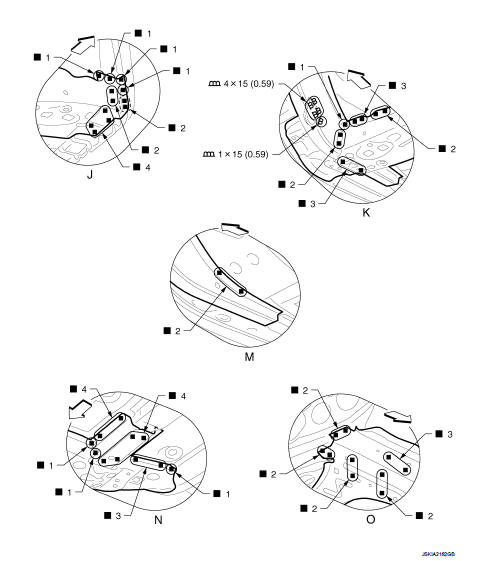
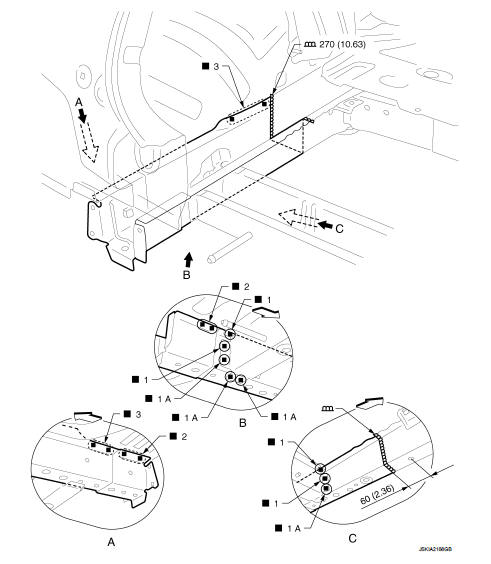
Front Side Member (2WD, RHD Models)
Work after radiator core support and hoodledge are removed.
 : Vehicle front
 : Weld the parts onto the back of
the component part.
Replacement parts
● Front side member assembly (LH)
● Front suspension mounting bracket
(LH Front)
● Engine mounting reinforcement
● Front side member reinforcement
assembly
● Tie down hook reinforcement
● Front side member closing plate assembly
(LH)
● Front towing hook reinforcement
● Add on frame bracket (LH)
● Front tie down hook
● Sensor harness bracket (LH)
● Front brake hose bracket (LH)
● Front suspension mounting bracket
(LH Rear)
 : Vehicle front
 : Weld the parts onto the back of
the component part.
View G: Before installing front suspension mounting bracket (Rear)
Unit: mm (in)
 : Vehicle front
 : Weld the parts onto the back of
the component part.
View M: Before installing front suspension mounting bracket (Rear)
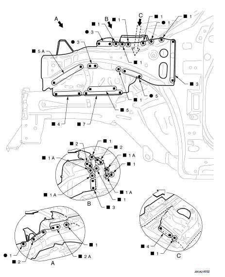
Front Side Member (2WD, LHD Models)
Work after radiator core support and hoodledge are removed.
: Vehicle front
: Weld the parts onto the back of the component part.
Replacement parts
● Front side member assembly (LH)
● Front suspension mounting bracket
(LH Front)
● Engine mounting reinforcement
● Front side member reinforcement
assembly
● Tie down hook reinforcement
● Front side member closing plate assembly
(LH)
● Front towing hook reinforcement
● Add on frame bracket
● Front tie down hook
● Sensor harness bracket (LH)
● Front brake hose bracket (LH)
● Front suspension mounting bracket
(LH Rear)
 : Vehicle front
 : Weld the parts onto the back of
the component part.
View G: Before installing front suspension mounting bracket (Rear)
Unit: mm (in)
 : Vehicle front
 : Weld the parts onto the back of
the component part.
View M: Before installing front suspension mounting bracket (Rear)
Front Side Member (4WD, RHD Models)
Work after radiator core support and hoodledge are removed.
 : Vehicle front
 : Weld the parts onto the back of
the component part.
Replacement parts
● Front side member assembly (LH)
● Front side member closing plate assembly
(LH)
● Front suspension mounting bracket
(LH Rear)
 : Vehicle front
 : Weld the parts onto the back of
the component part.
View D and H: Before installing front suspension mounting bracket (Rear)
Front Side Member (4WD, LHD Models)
Work after radiator core support and hoodledge are removed.
 : Vehicle front
 : Weld the parts onto the back of
the component part.
Replacement parts
● Front side member assembly (LH)
● Front side member closing plate assembly
(LH)
● Front suspension mounting bracket
(LH Rear)
 : Vehicle front
 : Weld the parts onto the back of
the component part.
View D and H: Before installing front suspension mounting bracket (Rear)
Front Side Member (2WD Models Partial Replacement)
Work after radiator core support is removed.
 : Vehicle front
 : Weld the parts onto the back of
the component part.
Replacement parts
● Front suspension mounting bracket
(RH Front)
● Add on frame bracket (RH)
POINT
The front side member on the left can also be replaced partially by butt welding.
Unit: mm (in)
 : Vehicle front
Replacement parts
● Front side member assembly (LH)
● Front side member closing plate assembly
(LH)
NOTE
:
For welding method and the number of welding points, refer to BRM-50, "Front
Side Member (2WD, RHD Models)" or BRM-53, "Front
Side Member (2WD, LHD Models)".
Front Side Member (4WD Models Partial Replacement)
Work after radiator core support is removed.
: Vehicle front
: Weld the parts onto the back of the component part.
Replacement parts
● Front suspension mounting bracket
(RH Front)
● Add on frame bracket (RH)
POINT
The front side member on the left can also be replaced partially by butt welding.
Unit: mm (in)
 : Vehicle front
Replacement parts
● Front side member assembly (LH)
● Front side member closing plate assembly
(LH)
NOTE
:
For welding method and the number of welding points, refer to BRM-56, "Front
Side Member (4WD, RHD Models)" or BRM-58, "Front
Side Member (4WD, LHD Models)".
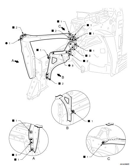
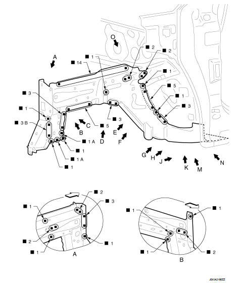
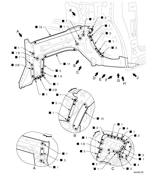
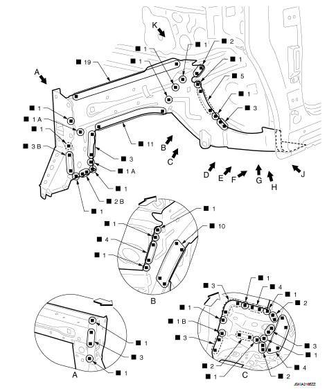
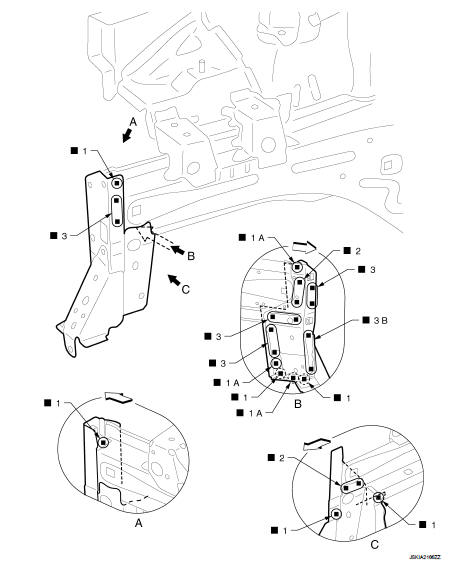
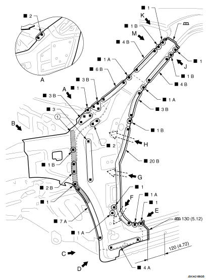
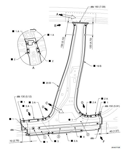
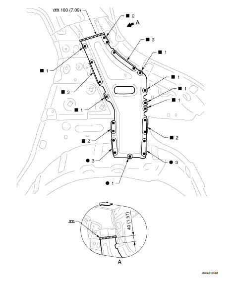
Front Pillar (RHD Models)
Work after hoodledge reinforcement is removed.
1. Body sealing
Unit: mm (in)
 : Vehicle front
Replacement parts
● Outer front side body (LH)
● Front pillar brace (LH)
● Side dash (LH)
● Upper inner front pillar (LH)
● Front fender bracket assembly (LH)
View A: Before installing outer front side body, front fender bracket assembly, and front pillar brace
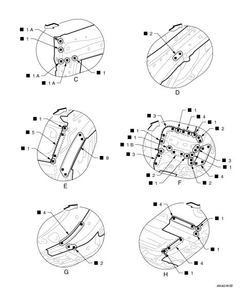
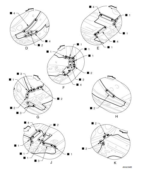
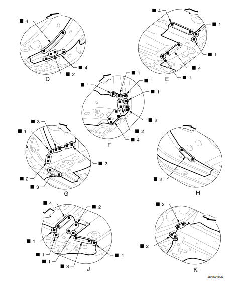
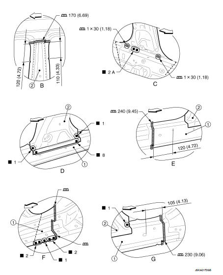
1. Urethane foam
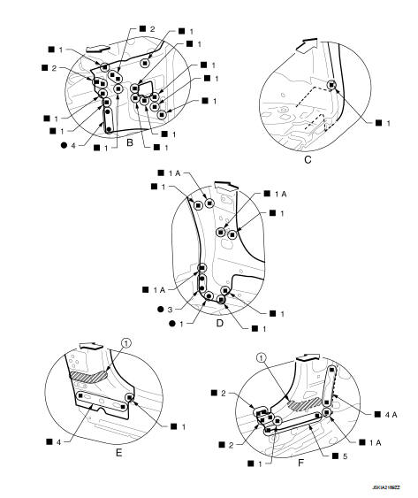
 : Vehicle front
 : Drill φ9 mm (0.35 in) hole for
the plug welding hole (ultra high strength steel plate).
 : Weld the parts onto the back of
the component part.
View E: Before installing outer front side body and front fender bracket
assembly
View G: Before installing outer front side body, front fender bracket assembly,
and front pillar brace
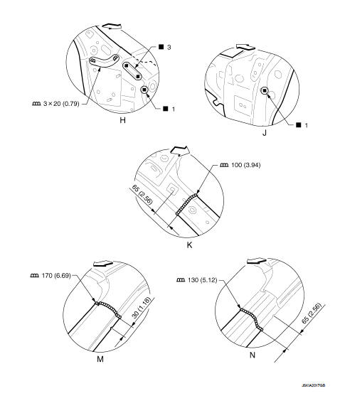
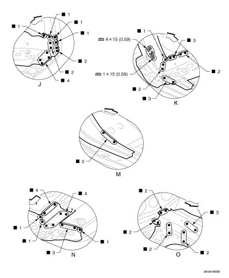
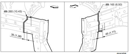
Unit: mm (in)
: Vehicle front
View N: Before installing outer front side body
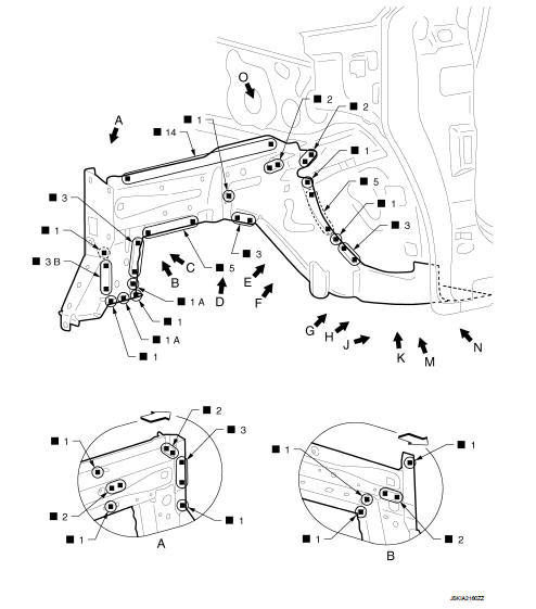
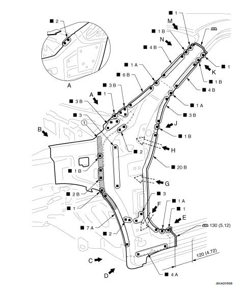
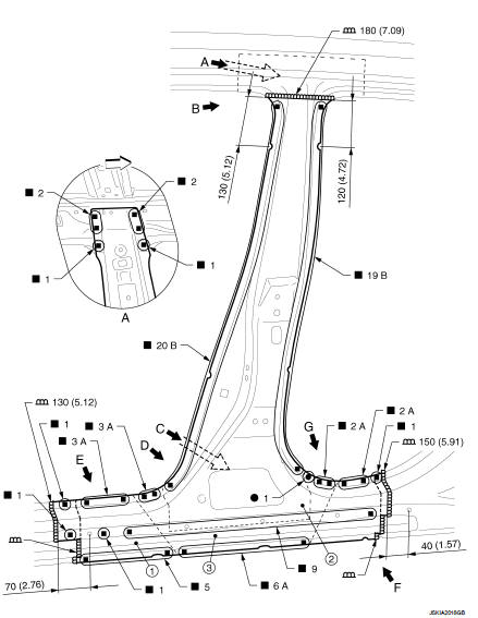
Front Pillar (LHD Models)
Work after hoodledge reinforcement is removed.
1. Body sealing
Unit: mm (in)
: Vehicle front
Replacement parts
● Outer front side body (LH)
● Front pillar brace (LH)
● Side dash (LH)
● Upper inner front pillar (LH)
● Front fender bracket assembly (LH)
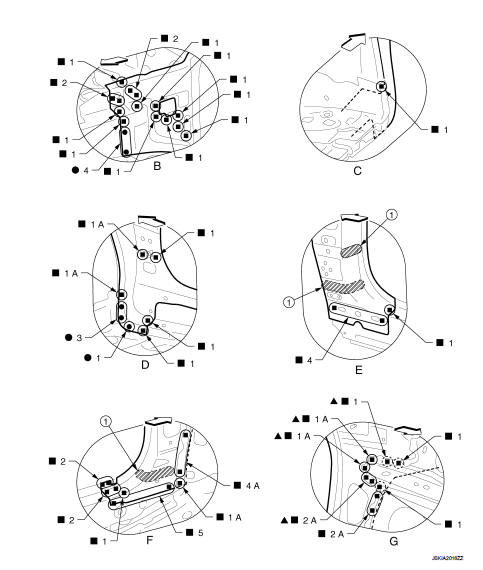
View A: Before installing outer front side body, front fender bracket assembly, and front pillar brace
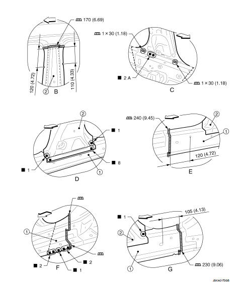
1. Urethane foam
: Vehicle front
View E: Before installing outer front side body and front fender bracket assembly
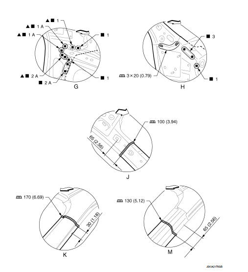
Unit: mm (in)
: Vehicle front
 : Drill φ9 mm (0.35 in) hole for
the plug welding hole (ultra high strength steel plate).
 : Weld the parts onto the back of
the component part.
View G: Before installing outer front side body, front fender bracket assembly, and front pillar brace View M: Before installing outer front side body
Center Pillar (2WD Models)
1. Outer sill reinforcement 2. Lower center pillar brace 3. Inner center pillar
Unit: mm (in)
: Vehicle front
Replacement parts
● Outer front side body (LH)
● Lower center pillar brace (LH)
● Inner center pillar (LH)
1. Outer sill reinforcement 2. Lower center pillar brace
Unit: mm (in)
: Vehicle front
View B, D, E, and G: Before installing outer front side body
Center Pillar (4WD Models)
1. Outer sill reinforcement 2. Lower center pillar brace 3. Inner center pillar
Unit: mm (in)
: Vehicle front
Replacement parts
● Outer front side body (LH)
● Lower center pillar brace (LH)
● Inner center pillar (LH)
1. Outer sill reinforcement 2. Lower center pillar brace
Unit: mm (in)
: Vehicle front
View B, D, E, and G: Before installing outer front side body
Outer Sill (Partial Replacement)
Unit: mm (in)
: Vehicle front
Replacement parts
● Outer sill (LH)
● Outer sill reinforcement (LH)
View A: Before installing outer sill
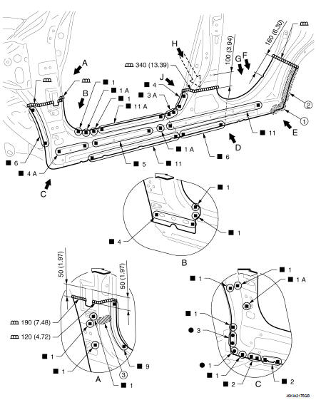
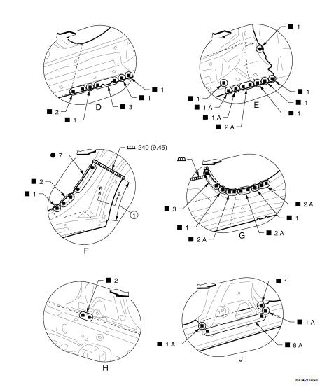
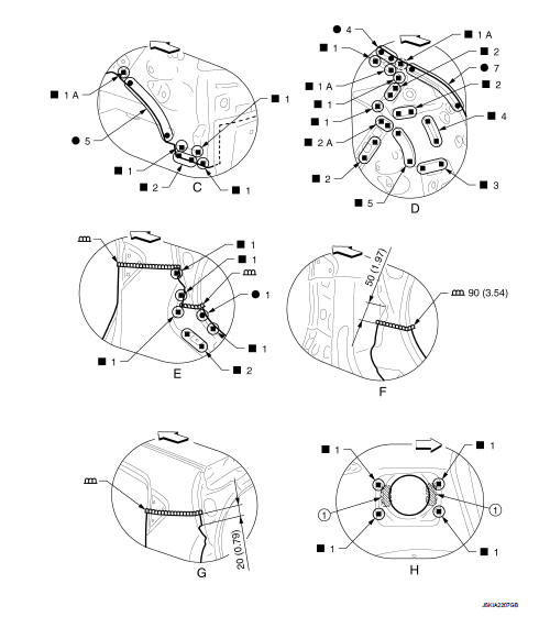
Outer Sill (RHD Models)
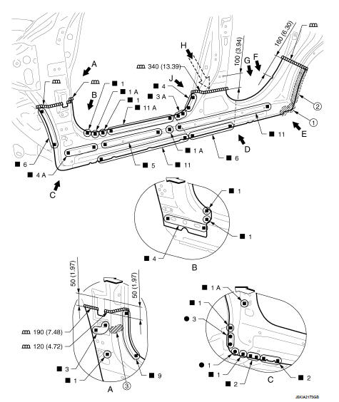
1. Body sealing
2. Adhesive
3. Urethane foam
Unit: mm (in)
 : Vehicle front
Replacement parts
● Outer sill (LH)
● Outer sill reinforcement (LH)
● Front fender bracket assembly (LH)
View B: Before installing outer sill
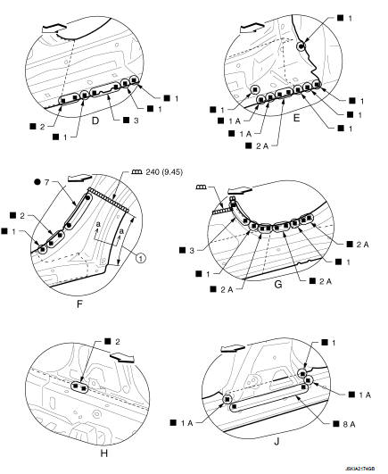
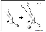
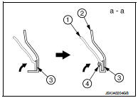
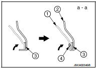
1. Hemming portion
Unit: mm (in)
 : Vehicle front
View J: Before installing outer sill POINT
• Perform the hemming to the flange of wheelarch after applying the adhesive.
• Apply the sealing to the flange end.
• Refer to BRM-40, "Rear Fender Hemming Process".
1. Outer rear wheelhouse
2. Rear fender
3. Adhesive
4. Sealant
Outer Sill (LHD Models)
1. Body sealing
2. Adhesive
3. Urethane foam
Unit: mm (in)
 : Vehicle front
Replacement parts
•
Outer sill (LH) •
Outer sill reinforcement (LH) •
Front fender bracket assembly (LH)
View B: Before installing outer sill
1. Hemming portion
Unit: mm (in)
 : Vehicle front
View J: Before installing outer sill POIN
• Perform the hemming to the flange of wheelarch after applying the adhesive.
• Apply the sealing to the flange end.
• Refer to BRM-40, "Rear Fender Hemming Process".
1. Outer rear wheelhouse
2. Rear fender
3. Adhesive
4. Sealant
Inner Sill
Work after outer sill is removed.
Remove the lower front pillar hinge brace (reusable).
1. Lower front pillar hinge brace
Unit: mm (in)
 : Vehicle front
 : Weld the parts onto the back of
the component part.
Replacement parts
● Inner sill (LH)
Unit: mm (in)
Vehicle front
: Weld the parts onto the back of
the component part.
View D: Before installing lower front pillar hinge brace
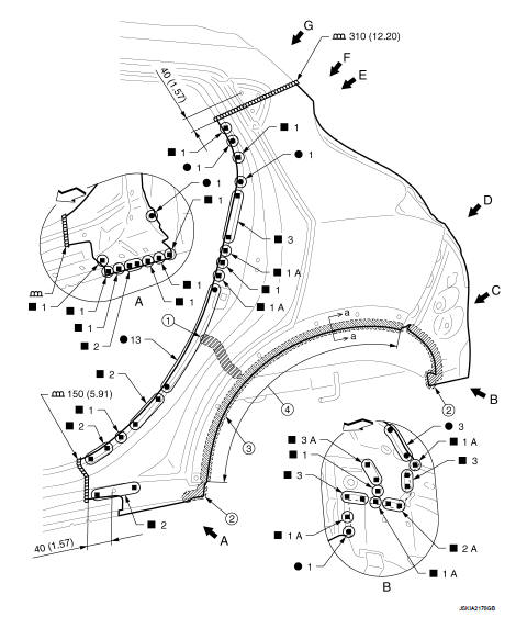
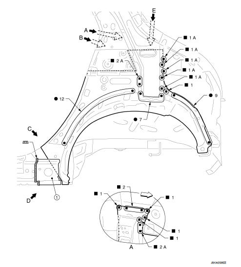
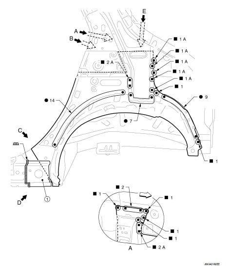
Rear Fender (2WD Models)
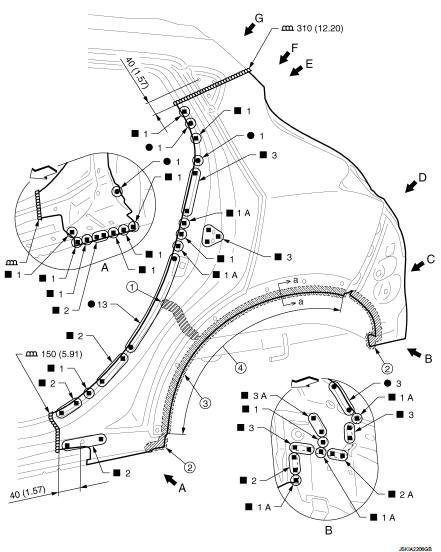
1. Urethane foam
2. Body sealing
3. Adhesive
4. Hemming portion
Unit: mm (in)
: Vehicle front
Replacement parts
● Rear fender (LH)
● Rear fender extension (LH)
● Rear fender corner (LH)
● Striker retainer
● Fuel filler base (Right side rear fender)
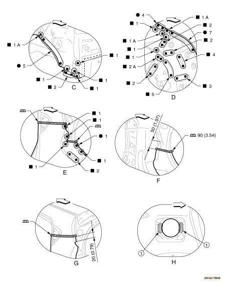
1. Adhesive
Unit: mm (in)
 : Vehicle front
 : Weld the parts onto the back of
the component part.
View F: Before installing rear fender View H: Right side rear fender
POINT
• Perform the hemming to the flange of wheelarch after applying the adhesive.
• Apply the sealing to the flange end.
• Refer to BRM-40, "Rear Fender Hemming Process".
1. Outer rear wheelhouse
2. Rear fender
3. Adhesive
4. Sealant
Rear Fender (4WD Models)
1. Urethane foam
2. Body sealing
3. Adhesive
4. Hemming portion
Unit: mm (in)
 : Vehicle front
Replacement parts
● Rear fender (LH)
● Rear fender extension (LH)
● Rear fender corner (LH)
1. Adhesive
Unit: mm (in)
 : Vehicle front
 : Weld the parts onto the back of
the component part.
View F: Before installing rear fender View H: Right side rear fender
POINT
• Perform the hemming to the flange of wheelarch after applying the adhesive.
• Apply the sealing to the flange end.
• Refer to BRM-40, "Rear Fender Hemming Process".
1. Outer rear wheelhouse
2. Rear fender
3. Adhesive
4. Sealant
Rear Fender Extension (2WD Models)
1. Body sealing
Replacement parts
● Rear fender corner (LH
Rear Fender Extension (4WD Models)
1. Body sealing
Replacement parts
● Rear fender corner (LH)
Rear Pillar Reinforcement
Work after rear fender is removed.
Unit: mm (in)
 : Vehicle front
 : Weld the parts onto the back of
the component part.
Replacement parts
● Inner rear pillar reinforcement (LH)
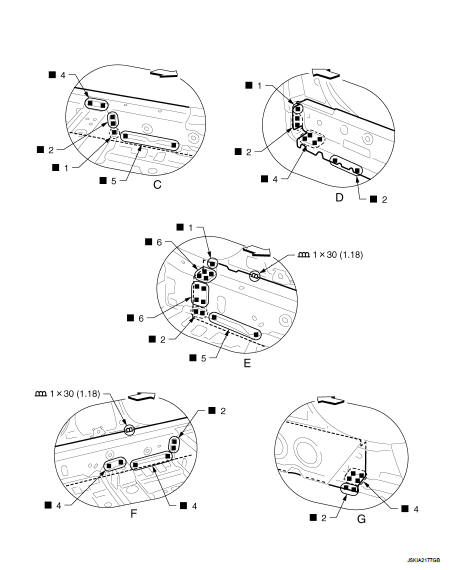
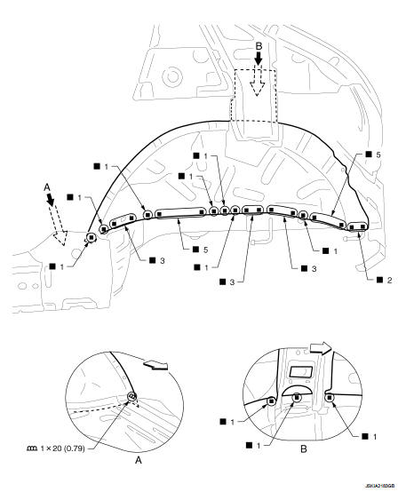
Outer Rear Wheelhouse (2WD Models)
Work after rear fender is removed.
Remove the outer sill reinforcement (reusable) for easier installation.
1. Outer sill reinforcement
 : Vehicle front
Replacement parts
● Outer rear wheelhouse (LH)
1. Outer sill reinforcement
Unit: mm (in)
 : Vehicle front
View C: Before installing outer sill reinforcement
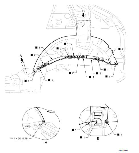
Outer Rear Wheelhouse (4WD Models)
Work after rear fender is removed.
Remove the outer sill reinforcement (reusable) for easier installation.
1. Outer sill reinforcement
 : Vehicle front
Replacement parts
● Outer rear wheelhouse (LH)
1. Outer sill reinforcement
Unit: mm (in)
 : Vehicle front
View C: Before installing outer sill reinforcement
Inner Rear Wheelhouse (2WD Models)
Work after rear fender, outer sill reinforcement, and outer rear wheelhouse are removed
Unit: mm (in)
: Vehicle front
Replacement parts
● Inner rear wheelhouse (LH)
Inner Rear Wheelhouse (4WD Models)
Work after rear fender, outer sill reinforcement, and outer rear wheelhouse are removed.
Unit: mm (in)
: Vehicle front
Replacement parts
● Inner rear wheelhouse (LH)
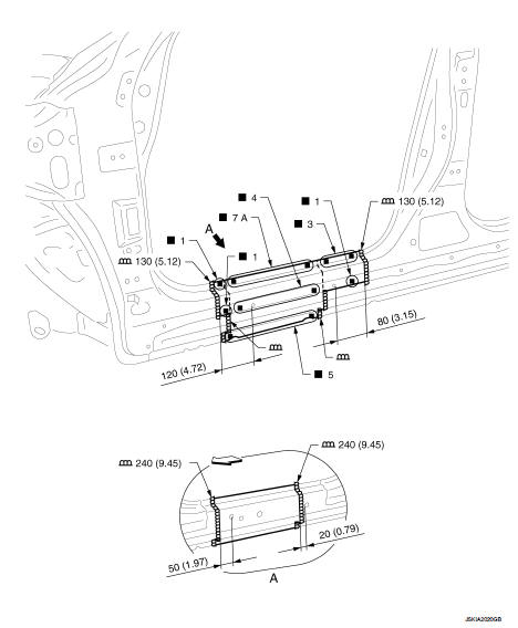
Rear Panel (2WD Models)
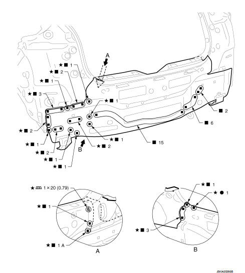
Unit: mm (in)
: Vehicle front
 : Welding method and the number of
welding points apply to both side of the vehicle.
Replacement parts
● Upper rear panel
Rear Panel (4WD Models)
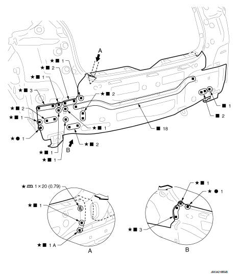
Unit: mm (in)
: Vehicle front
: Welding method and the number of
welding points apply to both side of the vehicle.
Replacement parts
● Upper rear panel
Inner Rear Pillar
Work after rear fender and inner rear pillar reinforcement are removed.
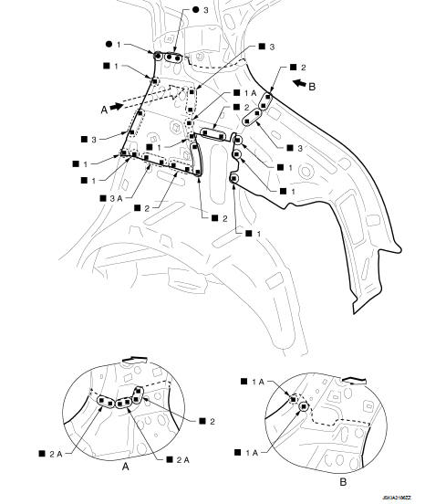
 : Vehicle front
 : Weld the parts onto the back of
the component part.
Replacement parts
● Inner rear pillar (LH)
● Rear pillar reinforcement (LH)
Rear Floor Rear (2WD Models)
Work after rear panel is removed.
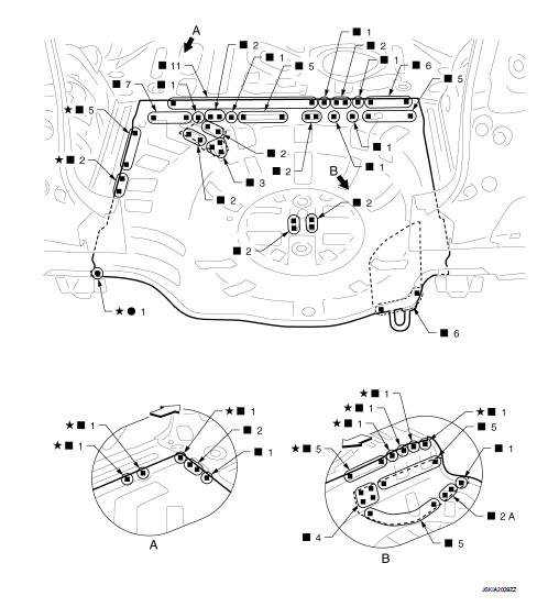
 : Vehicle front
 : Welding method and the number of
welding points apply to both side of the vehicle.
 : Weld the parts onto the back of
the component part.
Replacement parts
● Rear floor rear
● Spare tire clamp bracket
● Rear towing hook bracket
● Muffler mounting bracket
Rear Floor Rear (4WD Models)
Work after rear panel is removed.
: Vehicle front
: Welding method and the number of
welding points apply to both side of the vehicle.
Replacement parts
● Rear floor rear
● Spare tire clamp bracket
● Jack mounting bracket
● Canister bracket
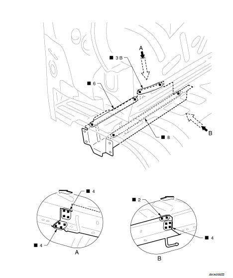
Rear Side Member (4WD Models Partial Replacement)
Work after rear panel and rear floor rear are removed.
Unit: mm (in)
: Vehicle front
 : Weld the parts onto the back of
the component part.
Replacement parts
● Rear side member assembly (LH)
Rear Side Member Extension (2WD Models)
Work after rear panel is removed.
Vehicle front
: Weld the parts onto the back of
the component part.
Replacement parts
● Rear side member extension (LH)
Rear Side Member Extension (4WD Models)
Work after rear panel is removed.
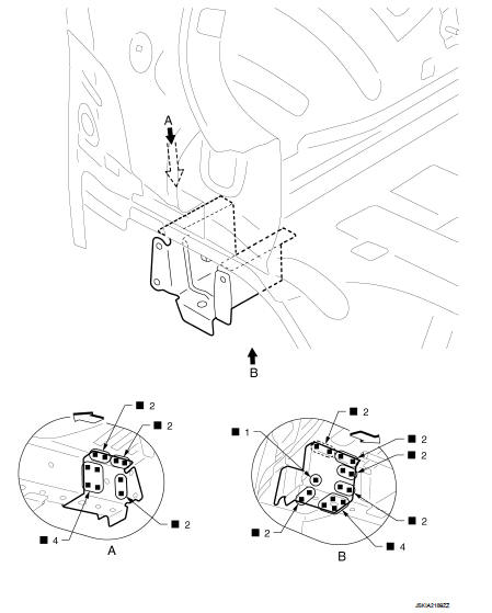
: Vehicle front
: Weld the parts onto the back of
the component part.
Replacement parts
● Rear side member extension (LH)
Roof
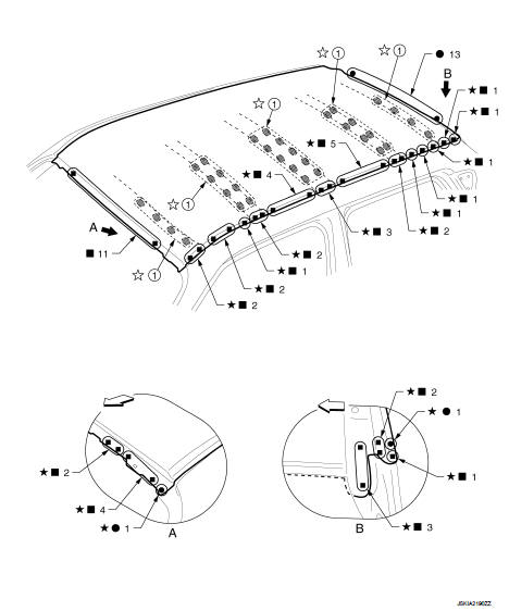
1. Body sealing
: Vehicle front
 : Welding method and the number of
welding points apply to both side of the vehicle.
 : Sealing portion apply to both
side of the vehicle.
Replacement parts
● Roof
● Roof bow No. 1
● Roof bow No. 2
● Roof bow No. 3
Roof Rail
Work after roof is removed.
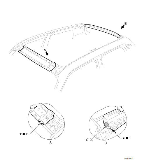
1. Adhesive
: Vehicle front
: Welding method and the number of
welding points apply to both side of the vehicle.
: Adhesive portion apply to both
side of the vehicle.
Replacement parts
● Front roof rail
● Rear roof rail
 Body construction
Body Construction (RHD Models)
1. Outer side body
2. Outer front pillar reinforcement
3. Upper inner front pillar
4. Lower dash
5. Hoodledge reinforcement
6. Lower front pillar hinge brace ...

Other materials:
Rear door finisher
Exploded View
1. Rear door panel
2. Grommet
3. Rear door corner cover inner
4. Cap
5. Power window switch finisher
6. Rear door finisher
: Clip
: Pawl
: Metal clip
Removal and Installation
REMOVAL
CAUTION:
• When removing, always use a remover tool that is made of plastic.
• Neve ...
B1001, B1002, B1003, B1004, B1005 diagnosis sensor unit
DTC Logic
DTC DETECTION LOGIC
DTC CONFIRMATION PROCEDURE
1.CHECK SELF-DIAG RESULT
With CONSULT-III
1. Turn ignition switch ON.
2. Perform “Self Diagnostic Result” mode of “AIR BAG” using CONSULT-III.
Without CONSULT-III
1. Turn ignition switch ON.
2. Check the air bag warning lamp statu ...
Door does not lock/unlock with keyfob
Diagnosis Procedure
1.CHECK POWER DOOR LOCK OPERATION
Check power door lock operation.
Does door lock/unlock with door lock and unlock switch?
YES >> GO TO 2.
NO >> Go to DLK-415, "ALL DOOR : Diagnosis Procedure".
2.CHECK REMOTE KEYLESS ENTRY RECEIVER
Check remote ...
