Nissan Juke Service and Repair Manual : Periodic maintenance
GEAR OIL
Inspection
OIL LEAKAGE
Make sure that gear oil is not leaking from transaxle or around it.
OIL LEVEL
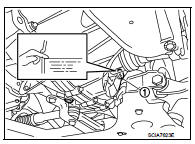
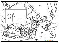
1. Remove filler plug (1) and gasket from transaxle case.
2. Check the oil level from filler plug mounting hole as shown in the figure.
CAUTION:
Never start engine while checking oil level.
3. Set a gasket on filler plug and then install it to transaxle case.
CAUTION:
Never reuse gasket.
4. Tighten filler plug to the specified torque. Refer to TM-88, "Exploded View".
Draining
1. Start engine and let it run to warm up transaxle.
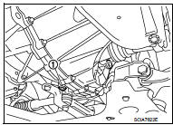
2. Stop engine. Remove drain plug (1) and gasket, using a socket [Commercial service tool] and then drain gear oil.
3. Set a gasket on drain plug and install it to clutch housing, using a socket [Commercial service tool].
CAUTION:
Never reuse gasket.
4. Tighten drain plug to the specified torque. Refer to TM-88, "Exploded View".
Refilling
1. Remove filler plug (1) and gasket from transaxle case.
2. Fill with new gear oil until oil level reaches the specified limit at filler plug mounting hole as shown in the figure.
Oil grade and viscosity : Refer to MA-13, "Fluids and Lubricants".
Oil capacity : Refer to TM-123, "General Specifications".
3. After refilling gear oil, check the oil level. Refer to TM-75, "Inspection".
4. Set a gasket on filler plug and then install it to transaxle case.
CAUTION:
Never reuse gasket.
5. Tighten filler plug to the specified torque. Refer to TM-88, "Exploded View".
 Symptom diagnosis
NOISE, VIBRATION AND HARSHNESS (NVH) TROUBLESHOOTING
NVH Troubleshooting Chart
Use the chart below to find the cause of the symptom. The numbers indicate
the order of the inspection. If necessary, ...

Other materials:
Electric controlled coupling oil seal
Exploded View
1. Rear final drive assembly
2. Electric controlled coupling oil seal
A. Oil seal lip
: Vehicle front
: Always replace after every
disassembly.
: Apply multi purpose grease
: Apply gear oil.
Removal and Installation
REMOVAL
1. Remove rear drive shafts. Refer to RAX-17, & ...
LAN System can system (type 11)
DTC/CIRCUIT DIAGNOSIS
Main line between IPDM-E and DLC circuit
Diagnosis Procedure
1.CHECK CONNECTOR
1. Turn the ignition switch OFF.
2. Disconnect the battery cable from the negative terminal.
3. Check the following terminals and connectors for damage, bend and loose
connection (connector s ...
P0131 A/F sensor 1
DTC Logic
DTC DETECTION LOGIC
To judge the malfunction, the diagnosis checks that the A/F signal computed
by ECM from the A/F sensor 1
signal is not inordinately low.
DTC CONFIRMATION PROCEDURE
1.PRECONDITIONING
If DTC Confirmation Procedure has been previously conducted, always turn
ign ...
