Nissan Juke Service and Repair Manual : Electric controlled coupling oil seal
Exploded View
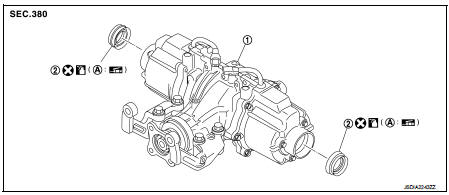
1. Rear final drive assembly 2. Electric controlled coupling oil seal
A. Oil seal lip
 : Vehicle front
 : Always replace after every
disassembly.
 : Apply multi purpose grease
 : Apply gear oil.
Removal and Installation
REMOVAL
1. Remove rear drive shafts. Refer to RAX-17, "Removal and Installation".
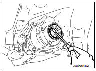
2. Remove electric controlled coupling oil seals from electric controlled coupling, using a suitable tool.
CAUTION:
Never damage electric controlled coupling.
INSTALLATION
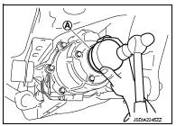
1. Install electric controlled coupling oil seals to electric controlled coupling, using the drift (A) (SST: KV38109700).
NOTE
:
The use of the special service tool satisfies the mounting dimensions.
CAUTION:
• Never reuse oil seals.
• When installing, never incline oil seals.
• Apply multi-purpose grease onto oil seal lips, and gear oil onto the circumference of oil seal.
2. Install rear drive shafts. Refer to RAX-17, "Removal and Installation".
3. When oil leaks while removing, check oil level after the installation. Refer to DLN-132, "Inspection".
 Electric controlled coupling
Exploded View
1. Sub-harness
2. Rear final drive assembly
3. Electric controlled coupling (right)
4. Reamer bolt
5. Electric controlled coupling (left)
A. Gear carrier mouting face
: Vehic ...
 Unit removal and installation
REAR FINAL DRIVE ASSEMBLY ...
Other materials:
General Specification
CAUTION:
• Use only Genuine NISSAN CVT Fluid NS-2. Never mix with other fluid.
• Using CVT fluid other than Genuine NISSAN CVT Fluid NS-2 will deteriorate in
driveability and CVT durability, and may damage
the CVT, which is not covered by the warranty.
*1: Refer to MA-13, "Fluids and Lu ...
Diagnosis system (EPS control unit)
Consult-III Function
FUNCTION
CONSULT-III can display each diagnostic item using the diagnostic test modes
shown following.
*: The following diagnosis information is erased by erasing.
• DTC
• Freeze frame data (FFD)
ECU IDENTIFICATION
Displays the part number stored in the control unit.
...
HVAC branch line circuit
Diagnosis Procedure
1.CHECK CONNECTOR
1. Turn the ignition switch OFF.
2. Disconnect the battery cable from the negative terminal.
3. Check the terminals and connectors of the A/C auto amp. for damage, bend and
loose connection (unit
side and connector side).
Is the inspection result norma ...
