Nissan Juke Service and Repair Manual : Electrical load signal
Description
The electrical load signal (Headlamp switch signal, rear window defogger switch signal, etc.) is transferred to ECM through the CAN communication line.
Component Function Check
1.CHECK REAR WINDOW DEFOGGER SWITCH FUNCTION
1. Turn ignition switch ON.
2. Select “DATA MONITOR” mode with CONSULT-III.
3. Select “LOAD SIGNAL” and check indication under the following conditions.
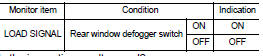
Is the inspection result normal? YES >> GO TO 2.
NO >> Go to EC-776, "Diagnosis Procedure".
2.CHECK LIGHTING SWITCH FUNCTION
Check “LOAD SIGNAL” indication under the following conditions.
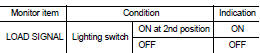
Is the inspection result normal? YES >> GO TO 3.
NO >> Go to EC-776, "Diagnosis Procedure".
3.CHECK HEATER FAN CONTROL SWITCH FUNCTION
Select “HEATER FAN SW” and check indication under the following conditions.
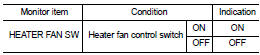
Is the inspection result normal? YES >> INSPECTION END
NO >> Go to EC-776, "Diagnosis Procedure".
Diagnosis Procedure
1.INSPECTION START
Confirm the malfunctioning circuit (rear window defogger, headlamp or heater fan). Refer to EC-776, "Component Function Check".
Which circuit is related to the incident? Rear window defogger>>GO TO 2 Headlamp>>GO TO 3.
Heater fan>>GO TO 4.
2.CHECK REAR WINDOW DEFOGGER SYSTEM
Perform trouble diagnosis of rear window defogger system. Refer to DEF-25, "Work Flow".
>> INSPECTION END
3.CHECK HEADLAMP SYSTEM
Perform trouble diagnosis of headlamp system. Refer to EXL-43, "Work Flow".
>> INSPECTION END
4.CHECK AIR CONDITIONING SYSTEM
Perform trouble diagnosis of air conditioning system. Check type of air conditioning system HAC-10, "Information" and refer to the follows.
• TYPE1: HAC-44, "Work Flow" • TYPE2: HAC-135, "Work Flow" • TYPE3: HAC-216, "Work Flow" • TYPE4: HAC-271, "Work Flow" • TYPE5: HAC-322, "Work Flow"
>> INSPECTION END
 Cooling fan
Component Function Check
1.CHECK COOLING FAN FUNCTION
With CONSULT-III
1. Turn ignition switch ON.
2. Perform “COOLING FAN” in “ACTIVE TEST” mode with CONSULT-III.
3. Touch “LOW” and “Hi” on the ...
 Fuel injector
Component Function Check
1.INSPECTION START
Turn ignition switch to START.
Is any cylinder ignited?
YES >> GO TO 2.
NO >> Go to EC-778, "Diagnosis Procedure".
2.CHECK ...
Other materials:
P0715 input speed sensor A
DTC Logic
DTC DETECTION LOGIC
DTC CONFIRMATION PROCEDURE
CAUTION:
Be careful of the driving speed.
1.PREPARATION BEFORE WORK
If another "DTC CONFIRMATION PROCEDURE" occurs just before, turn ignition
switch OFF and wait for at
least 10 seconds, then perform the next test.
> ...
Door does not lock/unlock with door lock and unlock
switch
All door
ALL DOOR : Description
All doors do not lock/unlock using door lock and unlock switch.
ALL DOOR : Diagnosis Procedure
1.CHECK DOOR LOCK AND UNLOCK SWITCH
Check door lock and unlock switch.
Refer to DLK-79, "DRIVER SIDE : Component Function Check".
Is the inspection resu ...
Radiator core support
HR16DE
HR16DE : Exploded View
1. Radiator core support upper
2. Air guide RH (MT models)
3. Radiator core support lower
4. Air guide LH 5. Air guide (upper)
6. Air guide LH (CVT models)
7. Air guide RH (CVT models)
: N·m (kg-m, ft-lb)
HR16DE : Removal and Installation
RADIATOR CORE SU ...
