Nissan Juke Service and Repair Manual : P0715 input speed sensor A
DTC Logic
DTC DETECTION LOGIC
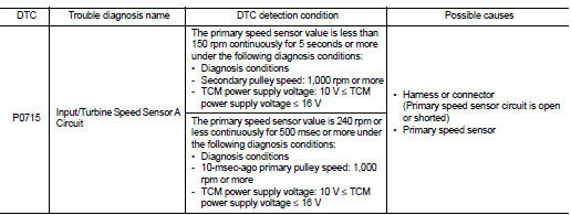
DTC CONFIRMATION PROCEDURE
CAUTION:
Be careful of the driving speed.
1.PREPARATION BEFORE WORK
If another "DTC CONFIRMATION PROCEDURE" occurs just before, turn ignition switch OFF and wait for at least 10 seconds, then perform the next test.
>> GO TO 2.
2.CHECK DTC DETECTION
1. Start the engine.
2. Drive the vehicle.
3. Maintain the following conditions for 10 seconds or more.
Selector lever : “L” POSITION Vehicle speed : 40 km/h (25 MPH) or more
4. Stop the vehicle.
5. Check the first trip DTC.
Is “P0715” detected? YES >> Go to TM-410, "Diagnosis Procedure".
NO >> INSPECTION END
Diagnosis Procedure
1.CHECK PRIMARY SPEED SENSOR POWER CIRCUIT
Check voltage between primary speed sensor harness connector terminal and ground.
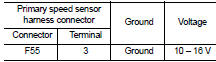
Is the check result normal? YES >> GO TO 6.
NO >> GO TO 2.
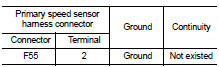
2.CHECK PRIMARY SPEED SENSOR GROUND CIRCUIT
Check continuity between primary speed sensor harness connector terminal and ground.
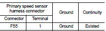
Is the check result normal? YES >> GO TO 3.
NO >> Repair or replace the malfunctioning parts.
3.CHECK CIRCUIT BETWEEN PRIMARY SPEED SENSOR AND TCM (PART 1)
1. Turn ignition switch OFF.
2. Disconnect the TCM connector.
3. Check continuity between primary speed sensor harness connector terminal and TCM harness connector terminal.
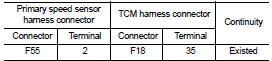
Is the check result normal? YES >> GO TO 4.
NO >> Repair or replace the malfunctioning parts.
4.CHECK CIRCUIT BETWEEN PRIMARY SPEED SENSOR AND TCM (PART 1)
Check continuity between primary speed sensor harness connector terminal and ground.
YES >> GO TO 5.
NO >> Repair or replace the malfunctioning parts.
5.CHECK TCM INPUT SIGNALS
1. Connect all of the disconnected connectors.
2. Lift the vehicle.
3. Start the engine.
4. Check frequency of primary speed sensor.
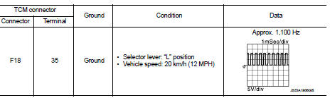
Is the check result normal? YES >> Check intermittent incident. Refer to GI-42, "Intermittent Incident".
NO >> Replace the primary speed sensor. TM-495, "Removal and Installation".
6.CHECK CIRCUIT BETWEEN IPDM E/R AND PRIMARY SPEED SENSOR (PART 1)
1. Disconnect the IPDM E/R connector.
2. Check continuity between IPDM E/R harness connector terminal and primary speed sensor harness connector terminal.
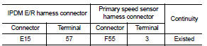
Is the check result normal? YES >> GO TO 7.
NO >> Repair or replace the malfunctioning parts.
7.CHECK CIRCUIT BETWEEN IPDM E/R AND PRIMARY SPEED SENSOR (PART 2)
Check continuity between IPDM E/R harness connector terminal and ground.
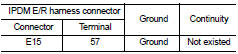
Is the check result normal? YES >> GO TO 8.
NO >> Repair or replace the malfunctioning parts.
8.DETECTION OF MALFUNCTION ITEMS
Check the following items: • Harness open circuit or short circuit between the ignition switch and IPDM E/R. Refer to PG-15, "Wiring Diagram - IGNITION POWER SUPPLY -".
• 10A fuse (No.55, IPDM E/R). Refer to PG-25, "Fuse, Connector and Terminal Arrangement".
• IPDM E/R Is the check result normal? YES >> Check intermittent incident. Refer to GI-42, "Intermittent Incident".
NO >> Repair or replace the malfunctioning parts.
 P0713 transmission fluid temperature sensor A
DTC Logic
DTC CONFIRMATION PROCEDURE
1.PREPARATION BEFORE WORK
If another "DTC CONFIRMATION PROCEDURE" occurs just before, turn ignition
switch OFF and wait for at
least 10 seconds, th ...
 P0720 output speed sensor
DTC Logic
DTC DETECTION LOGIC
DTC CONFIRMATION PROCEDURE
CAUTION:
Be careful of the driving speed.
1.PREPARATION BEFORE WORK
If another "DTC CONFIRMATION PROCEDURE" occurs just befor ...
Other materials:
Wiring diagram
BCM
LHD
LHD : Wiring Diagram
For connector terminal arrangements, harness layouts, and alphabets in a
(option abbreviation; if not
described in wiring diagram), refer to GI-12, "Connector Information/Explanation
of Option Abbreviation".
RHD
RHD : Wiring Diagram
For con ...
Hazard function
Component Function Check
1.CHECK FUNCTION
1. Select “MULTI REMOTE ENT” of “BCM” using CONSULT-III.
2. Select “FLASHER” in “ACTIVE TEST” mode.
3. Check that the function operates normally according to the following
conditions.
Is the inspection result normal?
YES >> Hazard warning lam ...
Rear door
Exploded View
1. Rear door panel
2. Door hinge (upper)
3. Door hinge (lower)
4. Door check link
5. Door striker
6. TORX bolt
: Do not reuse
: N·m (kg-m, in-lb)
N·m (kg-m, ft-lb)
: Body grease
Door assembly
DOOR ASSEMBLY : Removal and Installation
CAUTION:
• Perform work with 2 w ...
