Nissan Juke Service and Repair Manual : Cooling fan
Component Function Check
1.CHECK COOLING FAN FUNCTION
 With CONSULT-III
1. Turn ignition switch ON.
2. Perform “COOLING FAN” in “ACTIVE TEST” mode with CONSULT-III.
3. Touch “LOW” and “Hi” on the CONSULT-III screen.
4. Check that cooling fan operates at each speed.
 Without CONSULT-III
1. Perform IPDM E/R auto active test and check cooling fan motor operation. Refer to PCS-12, "Diagnosis Description" (WITH I-KEY) or PCS-43, "Diagnosis Description" (WITHOUT I-KEY).
2. Check that cooling fan operates at each speed.
Is the inspection result normal? YES >> INSPECTION END
NO >> Refer to EC-774, "Diagnosis Procedure".
Diagnosis Procedure
1.CHECK GROUND CONNECTION
1. Turn ignition switch OFF.
2. Check ground connection E21 and E38. Refer to Ground Inspection in GI-44, "Circuit Inspection".
Is the inspection result normal? YES >> GO TO 2.
NO >> Repair or replace ground connection.
2.CHECK COOLING FAN MOTOR CIRCUIT
1. Disconnect cooling fan motor harness connector.
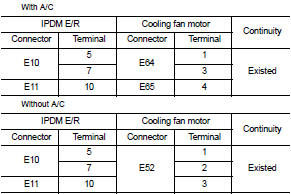
2. Check the continuity between IPDM E/R harness connector and cooling fan motor harness connector.
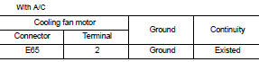
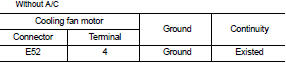
3. Check the continuity between cooling fan motor harness connector and ground.
4. Also check harness for short to ground and short to power.
YES or NO YES >> GO TO 4.
NO >> GO TO 3.
3.DETECT MALFUNCTIONING PART
Check the following.
• Harness for open or short between cooling fan motor and IPDM E/R • Harness for open or short between cooling fan motor and ground
>> Repair open circuit or short to ground or short to power in harness or connectors.
4.CHECK COOLING FAN MOTOR
Refer to EC-775, "Component Inspection".
YES or NO YES >> GO TO 5.
NO >> Replace cooling fan motor.
5.CHECK INTERMITTENT INCIDENT
Perform GI-42, "Intermittent Incident".
YES or NO YES >> Replace IPDM E/R. Refer to PCS-34, "Exploded View" (WITH I-KEY) or PCS-63, "Exploded View" (WITHOUT I-KEY).
NO >> Repair or replace harness or connector.
Component Inspection
1.CHECK COOLING FAN MOTOR
1. Turn ignition switch OFF.
2. Disconnect cooling fan motor harness connector E62.
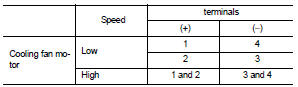
3. Supply cooling fan motor terminals with battery voltage and check operation.
Is the inspection result normal? YES >> INSPECTION END
NO >> Replace cooling fan motor.
 Clutch pedal position switch
Component Function Check
1.CHECK CLUTCH PEDAL POSITION SWITCH FUNCTION
With CONSULT-III
1. Turn ignition switch ON.
2. Select “ENGINE” using CONSULT-III.
3. Select “CLUTCH P/P SW” in “DATA MONITO ...
 Electrical load signal
Description
The electrical load signal (Headlamp switch signal, rear window defogger
switch signal, etc.) is transferred to
ECM through the CAN communication line.
Component Function Check
1.CHE ...
Other materials:
P17B4 low brake solenoid
DTC Logic
DTC DETECTION LOGIC
DTC CONFIRMATION PROCEDURE
1.PREPARATION BEFORE WORK
If another "DTC CONFIRMATION PROCEDURE" occurs just before, turn ignition
switch OFF and wait for at
least 10 seconds, then perform the next test.
>> GO TO 2.
2.CHECK DTC DETECTION
1. S ...
IGN off interlock door unlock function does not operate
Diagnosis Procedure
1.CHECK “AUTOMATIC LOCK/UNLOCK SELECT” SETTING IN “WORK SUPPORT”
1. Select “DOOR LOCK” of “BCM” using CONSULT-III.
2. Select “AUTOMATIC LOCK/UNLOCK SELECT” in “WORK SUPPORT” mode.
3. Check “AUTOMATIC LOCK/UNLOCK SELECT” in “WORK SUPPORT”.
Refer to DLK-371, "DOOR LOCK ...
Structure and operation
Sectional View
1. Transfer cover
2. Ring gear shaft
3. Companion flange
4. Drive pinion
5. Ring gear
6. Transfer case
Operation Principle
POWER TRANSFER DIAGRAM
1. Engine
2. Transaxle
3. Transfer
4. Propeller shaft
5. Electric controlled coupling
6. Rear final drive
ELECTR ...
