Nissan Juke Service and Repair Manual : Wiring diagram
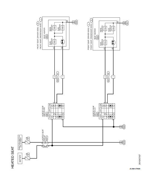
HEATED SEAT SYSTEM
Wiring Diagram
For connector terminal arrangements, harness layouts, and alphabets in a
 (option abbreviation; if not
described in wiring diagram), refer to GI-12, "Connector Information/Explanation
of Option Abbreviation".
 System
HEATED SEAT SYSTEM : System Description
Heated seat is a system that operates when ignition switch is in ON position.
HEATER OPERATION
• When the heated seat switch is ON, seat cushion heater a ...
 Symptom diagnosis
Squeak and rattle trouble diagnoses
Work Flow
CUSTOMER INTERVIEW
Interview the customer if possible, to determine the conditions that exist
when the noise occurs. Use the Diagnostic
Worksheet ...
Other materials:
Steering switch signal B circuit
Description
Transmits the steering switch signal to NAVI control unit.
Diagnosis Procedure
1.CHECK STEERING SWITCH SIGNAL B CIRCUIT
1. Disconnect NAVI control unit connector and spiral cable connector.
2. Check continuity between NAVI control unit harness connector and spiral cable
harness co ...
Exploded View
1. Main muffler
2. Mounting rubber
3. Ring gasket
4. Center tube
5. Exhaust gas temperature sensor 2
6. Diesel particulate filter assembly
7. Gasket
8. Stud bolt
9. Diesel particulate filter inlet tube
10. Gasket
A. To exhaust manifold
B. To pressure hose
: N·m (kg-m, ft-lb)
: ...
Door lock and unlock switch
Driver side : Component Function Check
1.CHECK FUNCTION
1. Select “DOOR LOCK” of “BCM” using CONSULT-III.
2. Select “CDL LOCK SW”, “CDL UNLOCK SW” in “DATA MONITOR” mode.
3. Check that the function operates normally according to the following
conditions.
Is the inspectio ...
