Nissan Juke Service and Repair Manual : Wiring diagram
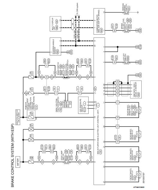
BRAKE CONTROL SYSTEM
Wiring Diagram
For connector terminal arrangements, harness layout, and alphabets in a
(option abbreviation; if not
described in wiring diagram), refer to GI-12, "Connector Information/Explanation
of Option Abbreviation".
 ECU diagnosis information
ABS actuator and electric unit (control unit)
Reference Value
CONSULT-III DATA MONITOR STANDARD VALUE
*1: Confirm tire pressure is standard value.
*2: Refer to “valve operation” in BRC-1 ...
 Basic inspection
...
Other materials:
P1574 ASCD vehicle speed sensor
Description
The ECM receives two vehicle speed sensor signals via CAN communication line.
One is sent from combination
meter, and the other is from TCM (Transmission control module). The ECM uses
these signals for ASCD
control. Refer to EC-477, "AUTOMATIC SPEED CONTROL DEVICE (ASCD) : Sy ...
Intelligent key
Component Function Check
1.CHECK FUNCTION
1. Select “INTELLIGENT KEY” of “BCM” using CONSULT-III.
2. Select “RKE OPE COUN1” in “DATA MONITOR” mode.
3. Check that the function operates normally according to the following
conditions.
Is the inspection result normal?
YES >& ...
Antenna base
Exploded View
1. Antenna rod
2. Antenna base
: N·m (kg-m, in-lb)
Removal and Installation
REMOVAL
1. Remove headlining. Refer to INT-26, "Exploded View".
2. Disconnect antenna feeder connector.
3. Remove nut to remove antenna base.
INSTALLATION
Install in the reverse order ...
