Nissan Juke Service and Repair Manual : Sectional View
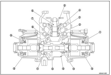
1. 4WD solenoid (RH)
2. Pinion rear bearing
3. Collapsible spacer
4. Pinion front bearing
5. Companion flange
6. Drive pinion
7. Gear carrier
8. Drive gear
9. 4WD solenoid (LH)
10. Electric controlled coupling (LH)
11. Side bearing (LH)
12. Center stem
13. Rear cover
14. Side bearing (RH)
15. Electric controlled coupling (RH)
 System description
STRUCTURE AND OPERATION ...
 Electric controlled coupling
The electric controlled coupling operates as the 4WD system. For the
operation, refer to DLN-15, "Operation
Principle". ...
Other materials:
Floor mats
WARNING
To avoid potential pedal interference that may result in a collision or injury:
• NEVER place a floor mat on top of another floor mat in the driver front
position.
• Use only genuine NISSAN floor mats specifically designed for use in your vehicle
model. See your NISSAN dealer for ...
Oil pump fitting bolt
Description
Replace the oil pump fitting bolt and the O-ring if oil leakage or exudes
from the oil pump fitting bol
Exploded View
1. Oil pump fitting bolt
2. O-ring
3. Transaxle assembly
: Always replace after every
disassembly.
: N·m (kg-m, ft-lb)
: Genuine NISSAN CVT Fluid NS-2
R ...
Blower fan resistor
Exploded View
1. Heater unit assembly
2. Fan control amp.*1
3. Blower fan resistor*2
4. Blower motor
5. Blower motor cover
• *1: Automatic air conditioner
• *2: Manual air conditioner or Manual heater
Removal and Installation
REMOVAL
1. Remove instrument panel assembly. Refer to I ...
