Nissan Juke Service and Repair Manual : Precaution for Brake System
WARNING:
Clean any dust from the front brake and rear brake with a vacuum dust collector.
Never blow with compressed
air.
• Brake fluid use refer to MA-13, "Fluids and Lubricants".
• Never reuse drained brake fluid.
• Never spill or splash brake fluid on painted surfaces. Brake fluid may seriously damage paint. Wipe it off immediately and wash with water if it gets on a painted surface. For brake component parts, never wash them with water.
• Always confirm the specified tightening torque when installing the brake pipes.
• After pressing the brake pedal more deeply or harder than normal driving, such as air bleeding, check each item of brake pedal. Adjust brake pedal if it is outside the standard value.
• Always clean with new brake fluid when cleaning the master cylinder, brake caliper and other components.
• Never use mineral oils such as gasoline or light oil to clean. They may damage rubber parts and cause improper operation.
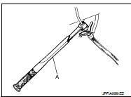
• Always loosen the brake tube flare nut with a flare nut wrench.
• Tighten the brake tube flare nut to the specified torque with a flare nut torque wrench (A).
• Turn the ignition switch OFF and disconnect the ABS actuator and electric unit (control unit) harness connector or the battery negative terminal before performing the work.
• Check that no brake fluid leakage is present after replacing the parts.
• Burnish the brake contact surfaces after refinishing or replacing rotors, after replacing pads, or if a soft pedal occurs at very low mileage.
- Front brake pad: Refer to BR-84, "BRAKE PAD : Inspection and Adjustment".
- Front disc rotor: Refer to BR-84, "DISC ROTOR : Inspection and Adjustment".
- Rear brake pad: Refer to BR-86, "BRAKE PAD : Inspection and Adjustment".
- Rear disc rotor: Refer to BR-86, "DISC ROTOR : Inspection and Adjustment".
 Precaution for Procedure without Cowl Top Cover
When performing the procedure after removing cowl top cover, cover
the lower end of windshield with urethane, etc.
...
 Preparation
Commercial Service Tool
...
Other materials:
Diagnosis system (BCM)
Common item : consult-III Function (BCM - COMMON ITEM)
APPLICATION ITEM
CONSULT-III performs the following functions via CAN communication with BCM.
SYSTEM APPLICATION
BCM can perform the following functions for each system.
NOTE:
It can perform the diagnosis modes except the following for ...
Horn function
Component Function Check
1.CHECK FUNCTION 1
1. Disconnect vehicle security horn relay.
2. Perform “VEHICLE SECURITY HORN” in “ACTIVE TEST” mode of “THEFT ALM” of “BCM”
using CONSULT-
III.
3. Check the horn operation.
Is the operation normal?
YES >> GO TO 2.
NO & ...
B2196 dongle unit
Description
BCM performs ID verification between BCM and dongle unit.
When verification result is OK, BCM permits cranking.
DTC Logic
DTC DETECTION LOGIC
DTC CONFIRMATION PROCEDURE
1.PERFORM DTC CONFIRMATION PROCEDURE
1. Turn ignition switch ON.
2. Turn ignition switch OFF.
3. Turn igni ...
