Nissan Juke Service and Repair Manual : P0380 glow rela
DTC Logic
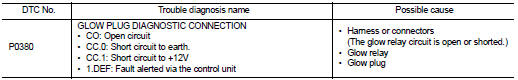
DTC DETECTION LOGIC
NOTE
:
If DTC P0380 is displayed with DTC P0560 or P0657, first perform trouble
diagnosis for DTC P0560 or P0657.
Refer to EC-963, "DTC Logic" (DTC P0560) or EC-976, "DTC Logic" (DTC P0657).
Diagnosis Procedure
1.CHECK GLOW RELAY POWER SUPPLY CIRCUIT
1. Turn ignition switch OFF.
2. Disconnect glow relay harness connector.
3. Turn ignition switch ON.
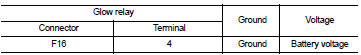
4. Check the voltage between glow relay connector and ground.
Is the inspection result normal? YES >> GO TO 3.
NO >> GO TO 2.
2.DETECT MALFUNCTIONING PART
Check the following.
• 100 A fusible link (letter B) • Harness for open and short between glow relay and battery
>> Repair open circuit or short to ground or short to power in harness or connectors.
3.CHECK GLOW RELAY INPUT CIRCUIT FOR OPEN AND SHORT-I
1. Turn ignition switch OFF.
2. Disconnect ECM harness connector.
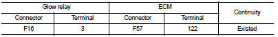
3. Check the continuity between glow relay harness connector and ECM harness connector.
4. Also check harness for short to ground and short to power.
Is the inspection result normal? YES >> GO TO 4.
NO >> Repair open circuit or short to ground or short to power in harness or connectors.
4.CHECK GLOW RELAY OUTPUT CIRCUIT FOR OPEN AND SHORT-II
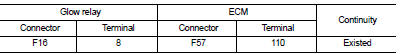
1. Check the continuity between glow relay harness connector and ECM harness connector.
2. Also check harness for short to ground and short to power.
Is the inspection result normal? YES >> GO TO 5.
NO >> Repair open circuit or short to ground or short to power in harness or connectors.
5.CHECK INTERMITTENT INCIDENT
Refer to GI-42, "Intermittent Incident", ???INCIDENT SIMULATION TESTS??? and ???GROUND INSPECTION???.
Is the inspection result normal? YES >> Replace glow relay.
NO >> Repair or replace.
 P0340 CMP sensor (phase)
DTC Logic
DTC DETECTION LOGIC
Diagnosis Procedure
1.CHECK GROUND CONNECTIONS
1. Turn ignition switch OFF.
2. Check ground connection E38. Refer to Ground inspection in GI-44, "Circuit
In ...
 P0402 EGR volume control valve
DTC Logic
DTC DETECTION LOGIC
Diagnosis Procedure
1.CHECK GROUND CONNECTIONS
1. Turn ignition switch OFF.
2. Check ground connection E38. Refer to Ground inspection in GI-44, "Circuit
In ...
Other materials:
Air breather hose
Removal and Installation
REMOVAL
1. Remove air cleaner case. Refer to EM-26, "Removal and Installation".
2. Remove clip from bracket.
3. Remove air breather hose from transaxle assembly.
INSTALLATION
Note the following, and install in the reverse order of removal.
CAUTION:
Chec ...
C1121, C1123, C1125, C1127 ABS out valve system
DTC Logic
DTC DETECTION LOGIC
DTC CONFIRMATION PROCEDURE
1.PRECONDITIONING
If “DTC CONFIRMATION PROCEDURE” has been previously conducted, always turn
ignition switch OFF and
wait at least 10 seconds before conducting the next test.
>> GO TO 2.
2.CHECK DTC DETECTION
With CON ...
Integrated control system (if so equipped)
The Integrated Control System is located below the audio system or navigation
system (if so equipped). Two Integrated Control System modes can be selected: Drive
mode and Climate Control mode.
Depending on which Integrated Control System mode is selected (Drive mode or
Climate Control mode), ...
