Nissan Juke Service and Repair Manual : P0335 CKP sensor (POS)
DTC Logic
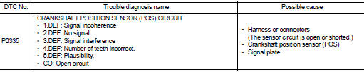
DTC DETECTION LOGIC
Diagnosis Procedure
1.CHECK GROUND CONNECTIONS
1. Turn ignition switch OFF.
2. Check ground connection E38. Refer to Ground inspection in GI-44, "Circuit Inspection".
Is the inspection result normal? YES >> GO TO 2.
NO >> Repair or replace ground connection.
2.CHECK CKP SENSOR (POS) GROUND CIRCUIT FOR OPEN AND SHORT
1. Turn ignition switch OFF.
2. Disconnect crankshaft position (CKP) sensor (POS) harness connector.
3. Disconnect ECM harness connector.
4. Check the continuity between CKP sensor (POS) harness connector and ECM harness connector
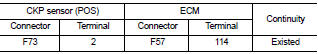
5. Also check harness for short to ground and short to power.
Is the inspection result normal? YES >> GO TO 3.
NO >> Repair open circuit or short to ground or short to power in harness or connectors.
3.CHECK CKP SENSOR (POS) INPUT SIGNAL CIRCUIT FOR OPEN AND SHORT
1. Check the continuity between CKP sensor (POS) harness connector and ECM harness connector.
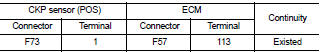
2. Also check harness for short to ground and short to power.
Is the inspection result normal? YES >> GO TO 4.
NO >> Repair open circuit or short to ground or short to power in harness or connectors.
4.CHECK CKP SENSOR (POS)
Refer to EC-933, "Component Inspection".
Is the inspection result normal? YES >> GO TO 5.
NO >> Replace crankshaft position sensor (POS).
5.CHECK GEAR TOOTH
Visually check for chipping flywheel gear tooth.
Is the inspection result normal? YES >> GO TO 6.
NO >> Replace signal plate.
6.CHECK INTERMITTENT INCIDENT
Refer to GI-42, "Intermittent Incident", ???INCIDENT SIMULATION TESTS??? and ???GROUND INSPECTION???.
>> INSPECTION END
Component Inspection
1.CHECK CKP SENSOR (POS)
1. Turn ignition switch OFF.
2. Disconnect CKP sensor (POS) harness connector.
3. Check resistance between CKP sensor (POS) terminals as follows.
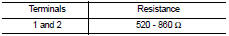
Is the inspection result normal? YES >> INSPECTION END
NO >> Replace CKP sensor.
 P0263, P0266, P0269, P0272 fuel injector
DTC Logic
DTC DETECTION LOGIC
NOTE:
Check injector code when the above DTC is indicated. If the code is normal,
replace injector showing an applicable
code. If the code is not normal, load inj ...
 P0340 CMP sensor (phase)
DTC Logic
DTC DETECTION LOGIC
Diagnosis Procedure
1.CHECK GROUND CONNECTIONS
1. Turn ignition switch OFF.
2. Check ground connection E38. Refer to Ground inspection in GI-44, "Circuit
In ...
Other materials:
5TH main gear assembly
Removal and Installation
REMOVAL
1. Shift the shifter lever to the 3rd gear position.
2. Disconnect the shifter cable and the selector cable from shifter lever A and
selector lever. Refer to TM-25,
"Removal and Installation".
CAUTION:
Never move shifter lever A and the selector l ...
ASCD main switch
Component Function Check
1.CHECK ASCD MAIN SWITCH FUNCTION
With CONSULT-III
1. Turn ignition switch ON.
2. Select “MAIN SW” in “DATA MONITOR” mode of “ENGINE” using CONSULT-III.
3. Check “MAIN SW” indication as per the following condition.
Without CONSULT-III
1. Turn ignitio ...
Floor mats
WARNING
To avoid potential pedal interference that may result in a collision or injury:
• NEVER place a floor mat on top of another floor mat in the driver front
position.
• Use only genuine NISSAN floor mats specifically designed for use in your vehicle
model. See your NISSAN dealer for ...
