Nissan Juke Service and Repair Manual : Option harness
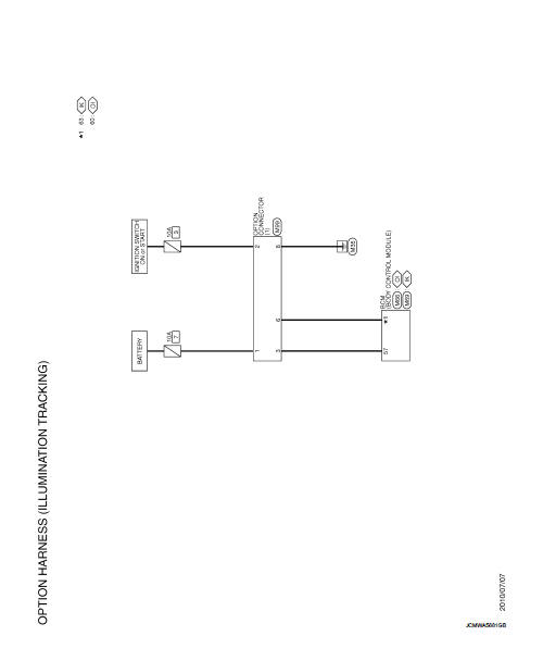
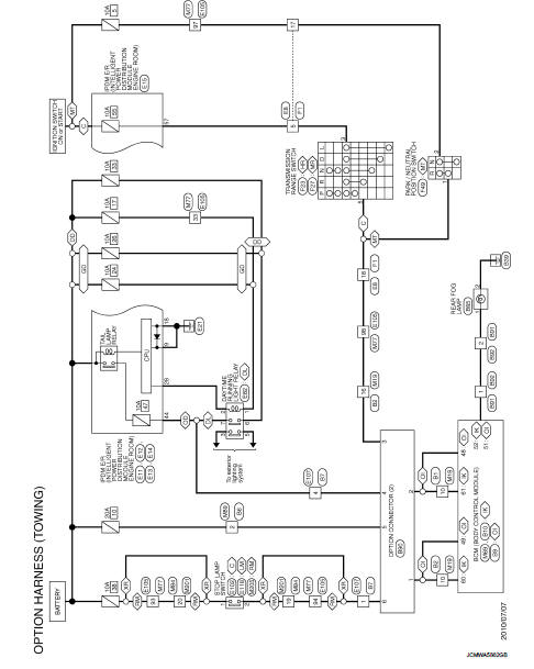
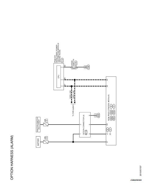
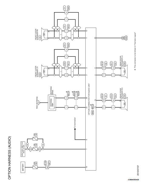
Wiring Diagram
For connector terminal arrangements, harness layouts, and alphabets in a
 (option abbreviation; if not
described in wiring diagram), refer to GI-12, "Connector Information/Explanation
of Option Abbreviation".
 Power supply routing circuit
Wiring Diagram - Battery power supply -
For connector terminal arrangements, harness layouts, and alphabets in a
(option abbreviation; if not
described in wiring diagram), refer to GI-12, "Con ...
 Fuse block - junction box (J/B)
Fuse, Connector and Terminal Arrangement
...
Other materials:
Corrosion protection
Description
To provide improved corrosion prevention, the following anti-corrosive
measures have been implemented in
NISSAN production plants. When repairing or replacing body panels, it is
necessary to use the same anti-corrosive
measures.
ANTI-CORROSIVE PRECOATED STEEL (GALVANNEALED STEE ...
Owner’s manual/service manual order information
Genuine NISSAN Service Manuals for this model year and prior can be purchased.
A genuine NISSAN Service Manual is the best source of service and repair information
for your vehicle. This manual is the same one used by the factory trained technicians
working at a NISSAN dealer. Genuine NISSAN O ...
P1652 starter motor system COMM
Description
ECM controls ON/OFF state of the starter relay, according to the engine and
vehicle condition. Models with no
Intelligent Key System transmit a control signal directly to IPDM E/R. On the
other hand, models with the Intelligent
Key System transmit a control signal to IPDM E/R by w ...
