Nissan Juke Service and Repair Manual : M&A branch line circuit
Diagnosis Procedure
1.CHECK CONNECTOR
1. Turn the ignition switch OFF.
2. Disconnect the battery cable from the negative terminal.
3. Check the terminals and connectors of the combination meter for damage, bend and loose connection (unit side and connector side).
Is the inspection result normal? YES >> GO TO 2.
NO >> Repair the terminal and connector.
2.CHECK HARNESS FOR OPEN CIRCUIT
1. Disconnect the connector of combination meter.
2. Check the resistance between the combination meter harness connector terminals.
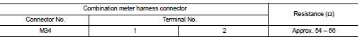
Is the measurement value within the specification? YES >> GO TO 3.
NO >> Repair the combination meter branch line.
3.CHECK POWER SUPPLY AND GROUND CIRCUIT
Check the power supply and the ground circuit of the combination meter. Refer to MWI-51, "COMBINATION METER : Diagnosis Procedure".
Is the inspection result normal? YES (Present error)>>Replace the combination meter. Refer to MWI-69, "Removal and Installation".
YES (Past error)>>Error was detected in the combination meter branch line.
NO >> Repair the power supply and the ground circuit.
 EPS branch line circuit
Diagnosis Procedure
1.CHECK CONNECTOR
1. Turn the ignition switch OFF.
2. Disconnect the battery cable from the negative terminal.
3. Check the terminals and connectors of the EPS control unit for ...
 STRG branch line circuit
Diagnosis Procedure
1.CHECK CONNECTOR
1. Turn the ignition switch OFF.
2. Disconnect the battery cable from the negative terminal.
3. Check the terminals and connectors of the steering angle senso ...
Other materials:
P1804, P1809 4WD control module
DTC Logic
DTC DETECTION LOGIC
DTC CONFIRMATION PROCEDURE
1.PRECONDITIONING
If “DTC CONFIRMATION PROCEDURE” has been previously conducted, always turn
ignition switch OFF and
wait at least 10 seconds before conducting the next test.
>> GO TO 2.
2.DTC REPRODUCTION PROCEDURE
W ...
Traction AA, A, B and C
The traction grades, from highest to lowest, are AA, A, B and C. Those grades
represent the tire’s ability to stop on wet pavement as measured under controlled
conditions on specified government test surfaces of asphalt and concrete. A tire
marked C may have poor traction performance.
WARNI ...
Cleaning
If your windshield is not clear after using the windshield washer or if a wiper
blade chatters when running, wax or other material may be on the blade or windshield.
Clean the outside of the windshield with a washer solution or a mild detergent.
Your windshield is clean if beads do not form whe ...
