Nissan Juke Service and Repair Manual : Liquid Gasket
REMOVAL OF LIQUID GASKET SEALING
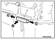
• After removing mounting nuts and bolts, separate the mating surface using the seal cutter [SST: KV10111100] (A) and remove old liquid gasket sealing.
CAUTION:
Be careful not to damage the mating surfaces.
• Tap the seal cutter [SST: KV10111100] to insert it (B), and then slide it (C) by tapping on the side as shown in the figure.
• In areas where the seal cutter [SST: KV10111100] is difficult to use, lightly tap the parts using a plastic hammer to remove it.
CAUTION:
If for some unavoidable reason tool such as a screwdriver is
used, be careful not to damage the mating surfaces.
LIQUID GASKET APPLICATION PROCEDURE
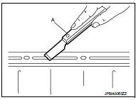
1. Using a scraper (A), remove old liquid gasket adhering to the liquid gasket application surface and the mating surface.
• Remove liquid gasket completely from the groove of the liquid gasket application surface, mounting bolts, and bolt holes.
2. Wipe the liquid gasket application surface and the mating surface with white gasoline (lighting and heating use) to remove adhering moisture, grease and foreign materials.
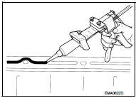
3. Attach liquid gasket tube to the tube presser (commercial service tool).
Use Genuine Liquid Gasket or equivalent.
4. Apply liquid gasket without gaps to the specified location according to the specified dimensions.
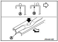
• If there is a groove for liquid gasket application, apply liquid gasket to the groove.
• As for bolt holes (B), normally apply liquid gasket inside the holes. Occasionally, it should be applied outside the holes.
Check to read the text of this manual.
A : Groove
 : Inside
• Within five minutes of liquid gasket application, install the mating component.
• If liquid gasket protrudes, wipe it off immediately.
• Do not retighten mounting bolts or nuts after the installation.
• After 30 minutes or more have passed from the installation, fill engine oil and engine coolant.
CAUTION:
If there are specific instructions in this manual, observe them
.
 Parts Requiring Angle Tightening
• Use the angle wrench [SST: KV10112100] for the final tightening of the
following engine parts:
- Camshaft sprocket (INT) bolt
- Cylinder head bolts
- Main bearing cap bolts
- Connecting rod ...
 Preparation
...
Other materials:
All-Wheel Drive (AWD) mode switch operations
AWD mode switch
The All-Wheel Drive (AWD) system is used to select the 2WD (Two-Wheel Drive),
AWD-V or AWD mode depending on the driving conditions.
The AWD mode indicator lights ( (green),
) are located in the instrument panel.
The AWD mode indicator lights (green)
illuminate when the ig ...
Diagnosis and repair workflow
Work Flow
OVERALL SEQUENCE
DETAILED FLOW
1.INTERVIEW FOR MALFUNCTION
Interview the symptom to the customer.
>> GO TO 2.
2.SYMPTOM CHECK
Check the symptom from the customer's information.
>> GO TO 3.
3.BASIC INSPECTION
Check the operation of each part. Check that any s ...
Rear seat belt
Exploded View
2WD models
1. Anchor bolt
2. Outer seat belt retractor RH
3. Shoulder anchor
4. Space
5. Retaining washer
6. Seat belt hook
7. Outer anchor
8. Outer seat belt retractor LH
9. Center seat belt finisher
10. Center seat belt buckle
11. RH seat belt buckle
12. Center ...
