Nissan Juke Service and Repair Manual : Instrument panel assembly
Exploded View
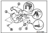
LHD models
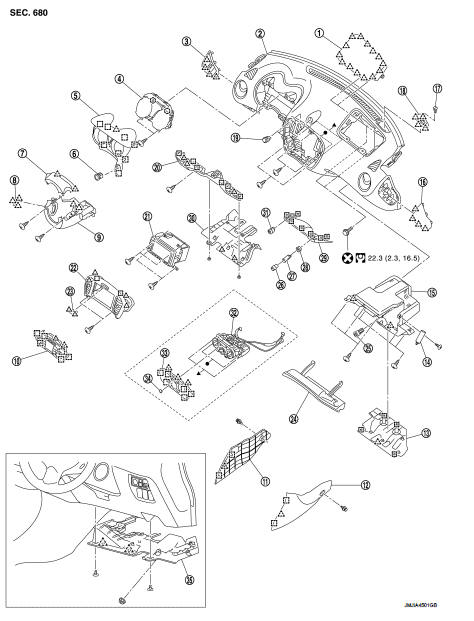
1. Front passenger air bag module
2. Instrument panel assembly
3. Instrument side finisher LH
4. Combination meter
5. Cluster lid A
6. Push-button ignition switch
7. Steering column upper cover
8. Steering lock escutcheon
9. Steering column lower cover
10. Multi display unit
11. Instrument lower cover LH
12. Instrument lower cover RH
13. Instrument under cover RH
14. Glove box dumper
15. Glove box assembly
16. Instrument side finisher RH
17. Sunload sensor
18. Switch panel
19. Hazard switch
20. Instrument lower panel LH
21. Audio unit or AV C/U
22. Cluster lid C
23. Warning lamp
24. Glove box lid
25. Front passenger air bag OFF switch
26. Socket knob
27. Inner socket
28. Socket ring
29. Cluster tray
30. USB connector
31. Instrument under cover LH
32. A/C controller (manual A/C)
33. A/C finisher (manual A/C)
34. Knob (manual A/C)
35. Instrument under cover RH (RHD
models)
 : Clip
 : Pawl
 : Metal clip
 : Do not reuse
 : N┬Ęm (kg-m, ft-lb)
Removal and Installation
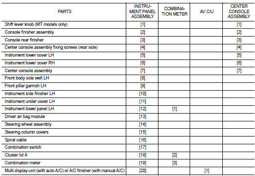
WORK STEP
When removing instrument panel assembly, combination meter, AV C/U, or center console assembly take steps in the order shown by the numbers below.
![[ ]: Number indicates step in removal procedure.](images/books/335/41/5.html16.jpg)
[ ]: Number indicates step in removal procedure.
WARNING:
Before servicing, turn ignition switch OFF, disconnect battery negative terminal
and wait 3 minutes or
more
.
REMOVAL
CAUTION:
When removing, always use a remover tool that is made of plastic.
1. Remove shift lever knob (MT models only).
ŌĆó 5MT models: Refer to TM-25, "Removal and Installation".
ŌĆó 6MT models: Refer to TM-78, "Removal and Installation".
2. Remove console finisher assembly.
1. Put selector lever in ŌĆ£NŌĆØ position.
2. Loosen the parking brake lever stroke by turning the adjusting nut with a socket wrench. Refer to PB- 2, "Inspection and Adjustment".
3. Lift up console finisher assembly in numerical order shown in the figure and disengage metal clips.
4. Remove console finisher assembly while pulling it towards vehicle rear.
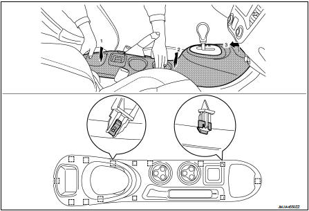
 : Metal clip
CAUTION:
ŌĆó Be careful not for damaging parts in surrounding area.
ŌĆó Remove metal clips slowly so that they are not damaged.
5. Disconnect seat heated switch harness connectors (with seat heated switch).
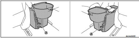
3. Remove console rear finisher.
1. Put front seat assembly (LH and RH) to frontmost position.
2. Pull back console rear finisher, and disengage the pawls and metal clips.
 : Pawl
: Metal clip
: Pawl
: Metal clip
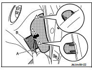
4. Remove center console assembly fixing screws (A).
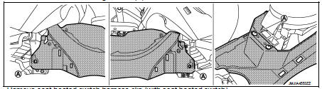
5. Remove instrument lower cover LH.
1. Put front seat assembly LH to rearmost position.
2. Remove fixing clip (A).
3. Pull the instrument lower cover LH crosswise, and disengage the pawl and metal clips.
CAUTION:
Remove pawl and metal clips slowly so that they are not
damaged.
 : Pawl
 : Metal clip
6. Remove instrument lower cover RH.
1. Put front seat assembly RH to rearmost position.
2. Remove fixing clip (A).
3. Pull the instrument lower cover RH crosswise, and disengage the pawl and metal clips.
CAUTION:
Remove pawl and metal clips slowly so that they are not
damaged.
 : Pawl
 : Metal clip
7. Remove center console assembly.
1. Remove center console fixing screws (A).
2. Remove seat heated switch harness clip (with seat heated switch).
3. Lift up center console assembly back side.
CAUTION:
Be careful not for damaging parts in surrounding area.
8. Release front pillar portion of front body side welt LH. Refer to INT-20, "BODY SIDE WELT : Removal and Installation".
9. Remove front pillar garnish LH. Refer to INT-18, "FRONT PILLAR GARNISH : Removal and Installation".
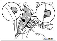
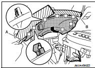
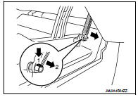
10. Remove instrument side finisher LH.
1. Insert remover tool (A) between instrument side finisher LH and instrument panel assembly to disengage the pawls as shown in the figure.
2. Pull back instrument side finisher LH.
 : Pawl
CAUTION: Apply protective tape (B) on the part to protect it from damage.
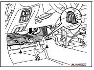
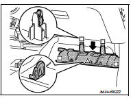
11. Remove instrument under cover LH.
1. Remove fixing clips (A).
2. Pull downward and disengage pawls.
 : Pawl
NOTE
:
RHD models
1. Remove fixing clips (A).
2. Remove fixing clip (B).
3. Pull downward and disengage pawls.
 : Pawl
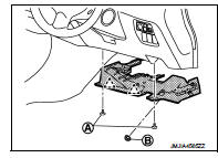
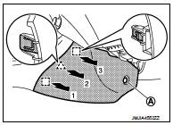
12. Remove instrument lower panel LH.
1. Remove hood opener and fuel lid opener lever. Refer to DLK-173, "HOOD LOCK CONTROL CABLE : Removal and Installation".
2. Remove fixing screw (A).
3. Pull back instrument lower panel LH, and then disengage the pawls and metal clips.
4. Disconnect harness connectors and aspirator duct.
 : Pawl
 : Metal clip
13. Remove driver air bag module. Refer to SR-13, "Removal and Installation".
14. Remove steering wheel. Refer to ST-9, "Removal and Installation".
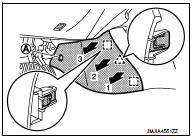
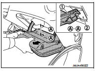
15. Remove steering column covers.
1. Place the tilt to the lowest level.
2. Remove steering lock escutcheon (1). (without Intelligent
Key)
3. Remove fixing screws (A).
4. Pull up steering column upper cover (2), and then disengage steering column upper cove fixing pawls.
5. Remove steering column upper cover.
6. Pull down the steering column lower cover (3), and then remove steering column lower cover.
 Pawl
Pawl
NOTE
:
Disengage the pawls, and then remove steering lock escutcheon
(4). (with Intelligent Key)
16. Remove spiral cable. Refer to SR-16, "Removal and Installation".
17. Remove combination switch. Refer to BCS-94, "Removal and Installation".
18. Remove cluster lid A.
1. Cover steering shaft with a shop cloth (A) to prevent damage.
2. Pull back cluster lid A while holding the lower side and disengage the metal clips underside.
3. Hold both upper sides of cluster lid A and pull it out towards vehicle rear, and disengage pawl and metal clips topside.
4. Disconnect push-button ignition switch harness connector and NATS antenna amp.harness connector. (with Intelligent Key)
 : Pawl
 : Metal clip
CAUTION:
Remove metal clips slowly so that they are not damaged.
19. Remove combination meter. Refer to MWI-69, "Removal and Installation".
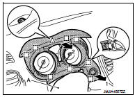
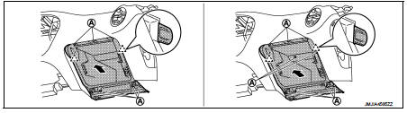
20. Remove multi display unit (with auto A/C) or A/C finisher (with manual A/C).
Multi display unit (with auto A/C) A/C finisher (with manual A/C)
: Pawl
 : Metal clip
ŌĆó Multi display unit (with auto A/C) - Insert a remover tool (A) between multi display unit (1) and instrument panel assembly (2), and then disengage pawls and metal clip.
- Pull back multi display unit, and then disconnect harness connector.
CAUTION:
Apply protective tape (B) on the part to protect it from damage.
ŌĆó A/C finisher (with manual A/C) - Remove intake door lever knob (3). Refer to HAC-239, "Removal and Installation".
- Insert a remover tool (A) between A/C finisher (4) and instrument panel assembly (5), and then disengage pawls and metal clip.
- Pull back A/C finisher.
CAUTION:
Apply protective tape (B) on the part to protect it from damage.
21. Remove A/C control fixing screws (with Manual A/C). Refer to HAC-239, "Removal and Installation".
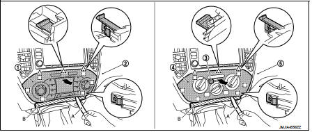
22. Remove cluster lid C.
1. Remove fixing screws (A).
2. Pull back cluster lid C, and disengage the pawls and metal clips.
3. Disconnect harness connector.
 : Pawl
 : Metal clip
23. Remove audio or NAVI control unit.
ŌĆó Audio unit: Refer to AV-38, "Removal and Installation".
ŌĆó NAVI control unit: Refer to AV-84, "Removal and Installation".
24. Disconnect hazard switch harness connector.
25. Remove cluster tray.
1. Insert a remover tool (A) between cluster tray and instrument panel assembly, and then pull downward and disengage metal clips.
2. Pull back cluster tray.
3. Disconnect harness connectors.
 : Metal clip
CAUTION:
Apply protective tape (B) on the part to protect it from damage.
26. Release front pillar portion of front body side welt RH. Refer to INT-20, "BODY SIDE WELT : Removal and Installation".
27. Remove front pillar garnish RH. Refer to INT-18, "FRONT PILLAR GARNISH : Removal and Installation".
28. Remove instrument side finisher RH.
1. Insert remover tool (A) between instrument side finisher RH and instrument panel assembly to disengage the pawls as shown in the figure.
2. Pull back instrument side finisher RH.
 : Pawl
CAUTION:
Apply protective tape (B) on the part to protect it from damage.
29. Remove instrument under cover RH.
1. Remove fixing clips (A).
2. Pull downward and disengage pawl and metal clips.
 Pawl
Pawl
 : Metal clip
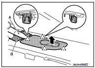
30. Remove glove box lid.
1. Open glove box lid.
2. Pull glove box lid (1) toward vehicle rear, and then disengage the joint from instrument panel assembly (2).
3. Disengage the pawl, and then remove damper pin on right side.
 : Pawl
CAUTION:
Never excessively pull string of glove box damper.
31. Remove glove box assembly.
2WD models
4WD models
1. Remove fixing screws (A).
2. Pull back the glove box cover assembly while holding the lower side and disengage the pawls.
 : Pawl
32. Remove front passenger air bag module. Refer to SR-19, "Removal and Installation".
33. Remove switch panel.
1. Insert remover tool (A) between switch panel and instrument panel assembly to disengage the pawls as shown in the figure.
2. Pull up switch panel, and then disconnect harness connector.
 : Pawl
CAUTION:
Apply protective tape (B) on the part to protect it from damage.
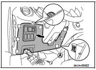
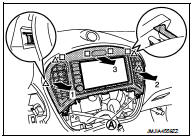
34. Remove instrument panel assembly mounting screws (A) and bolts (B).
CAUTION:
Cover tool with a shop cloth to prevent windshield glass from being damaged.
35. Remove instrument panel assembly.
1. Disengage harness (A) and harness (B) of front pillar LH and RH portions from instrument panel assembly.
2. Remove instrument panel from passenger door opening portion.
CAUTION:
ŌĆó Cover CVT shift selector upper surface with a shop cloth to prevent it from
being damaged.
ŌĆó When removing instrument panel assembly, 2 workers are required to prevent it from dropping.
36. Remove the following parts after removing instrument panel assembly.
ŌĆó Side defrostor nozzle: Refer toVTL-10, "SIDE DEFROSTER NOZZLE : Removal and Installation".
ŌĆó Side ventilator grille: Refer to VTL-11, "SIDE VENTILATOR GRILLE : Removal and Installation".
ŌĆó Side defrostor grille: VTL-11, "SIDE DEFROSTER GRILLE : Removal and Installation".
ŌĆó Front defrostor nozzle: VTL-11, "FRONT DEFROSTER NOZZLE : Removal and Installation".
ŌĆó Center ventilator duct: VTL-12, "CENTER VENTILATOR DUCT : Removal and Installation".
ŌĆó Side ventilator duct: VTL-12, "SIDE VENTILATOR DUCT : Removal and Installation".
ŌĆó GPS antenna: AV-89, "Removal and Installation".
ŌĆó Hazard switch: EXL-97, "Removal and Installation".
INSTALLATION
Note the following item, and then install in the reverse order of removal.
CAUTION:
After installation, adjust the parking brake lever stroke. Refer to PB-2,
"Inspection and Adjustment".

 Center console assembly
Exploded View
CVT models
1. Console indicator finisher
2. Instrument lower cover RH
3. Center console assembly
4. Instrument lower cover LH
5. Instrument stay
6. CVT shift selector assemb ...
Other materials:
Cup holders
CAUTION
ŌĆó Avoid abrupt starting and braking when the cup holder is being used
to prevent spilling the drink. If the liquid is hot, it can scald you or your passenger.
ŌĆó Use only soft cups in the cup holder.
Hard objects can injure you in an accident.
Center console
Door (front a ...
Accelerator pedal released position learning
Description
Accelerator Pedal Released Position Learning is a function of ECM to learn
the fully released position of the
accelerator pedal by monitoring the accelerator pedal position sensor output
signal. It must be performed each
time harness connector of accelerator pedal position sensor ...
Fuel injector
Component Function Check
1.INSPECTION START
Turn ignition switch to START.
Is any cylinder ignited?
YES >> GO TO 2.
NO >> Go to EC-778, "Diagnosis Procedure".
2.CHECK FUEL INJECTOR FUNCTION
With CONSULT-III
1. Start engine.
2. Perform ŌĆ£POWER BALANCEŌĆØ in ŌĆ£AC ...
