Nissan Juke Owners Manual : Headlights
Fog may temporarily form inside the lens of the exterior lights in the rain or in a car wash. A temperature difference between the inside and the outside of the lens causes the fog. This is not a malfunction. If large drops of water collect inside the lens, contact a NISSAN dealer.
Replacing
Halogen headlight model:
The headlight is a semi-sealed beam type which uses a replaceable headlight (halogen) bulb.
CAUTION
• Do not leave the bulb out of the headlight reflector for a long period of time. Dust, moisture, smoke, etc.
entering the headlight body may affect bulb performance.
• High pressure halogen gas is sealed inside the halogen bulb. The bulb may break if the glass envelope is scratched or the bulb is dropped.
• Only touch the base when handling the bulb. Never touch the glass envelope. Touching the glass envelope could significantly affect bulb life and/or headlight performance.
• Aiming is not necessary after replacing the bulb. When aiming adjustment is necessary, contact a NISSAN dealer.
Use the same number and wattage as originally installed as shown in the chart.
Disconnect the battery negative cable before replacing bulbs.
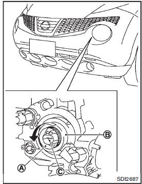
1. Remove the connector.
2. Turn the holderA and then pull out it.
Remove the cap B and then remove the bulbC .
 Lights
1. Map light
2. Front side marker light
3. Front fog light (if so equipped)
4. Headlight (high-beam/low-beam)
5. Front turn signal light
6. Front parking light
7. Side turn signal light
8. Da ...
 Exterior and interior lights
: See a NISSAN dealer for replacement.
NOTE: Always check with the Parts Department at a NISSAN dealer for the latest
information about parts.
: REMOVE
: INSTALL
Replacement procedures
All ...
Other materials:
The braking distance is long
Description
Brake stopping distance is long when ABS function is operated.
Diagnosis Procedure
CAUTION:
Brake stopping distance on slippery road like rough road, gravel road or snowy
road may become
longer when ABS is operated than when ABS is not operated.
1.CHECK BRAKING FORCE
Check bra ...
B1033, B1034 crash zone sensor
DTC Logic
DTC DETECTION LOGIC
DTC CONFIRMATION PROCEDURE
1.CHECK SELF-DIAG RESULT
With CONSULT-III
1. Turn ignition switch ON.
2. Perform “Self Diagnostic Result” mode of “AIR BAG” using CONSULT-III.
Without CONSULT-III
1. Turn ignition switch ON.
2. Check the air bag warning la ...
B1202, B1203, B1204, B1205, B1206, B1207 diagnosis sensor unit
DTC Logic
DTC DETECTION LOGIC
DTC CONFIRMATION PROCEDURE
1.CHECK SELF-DIAG RESULT
With CONSULT-III
1. Turn ignition switch ON.
2. Perform “Self Diagnostic Result” mode of “AIR BAG” using CONSULT-III.
Without CONSULT-III
1. Turn ignition switch ON.
2. Check the air bag warning la ...
