Nissan Juke Service and Repair Manual : General Precauti
• Always use a 12 volt battery as power source.
• Do not attempt to disconnect battery cables while engine is running.
• Before connecting or disconnecting the ECM harness connector, turn ignition switch OFF and disconnect negative battery cable. Failure to do so may damage the ECM because battery voltage is applied to ECM even if ignition switch is turned OFF.
• Before removing parts, turn ignition switch OFF and then disconnect battery ground cable.
• Do not disassemble ECM.
• If a battery cable is disconnected, the memory will return to the ECM value.
The ECM will now start to self-control at its initial value.
Engine operation can vary slightly when the terminal is disconnected.
However, this is not an indication of a malfunction.
Do not replace parts because of a slight variation.
• If the battery is disconnected, the following emission-related diagnostic information will be lost within 24 hours.
- Diagnostic trouble codes
- 1st trip diagnostic trouble codes
- Freeze frame data
- 1st trip freeze frame data
- System readiness test (SRT) codes
- Test values
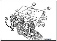
• When connecting ECM harness connector (1), fasten (B) it securely with a lever as far as it will go as shown in the figure.
2. ECM
A. Loosen
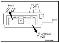
• When connecting or disconnecting pin connectors into or from ECM, take care not to damage pin terminals (bend or break).
Make sure that there are not any bends or breaks on ECM pin terminal, when connecting pin connectors.
• Securely connect ECM harness connectors.
A poor connection can cause an extremely high (surge) voltage to develop in coil and condenser, thus resulting in damage to ICs.
• Keep engine control system harness at least 10 cm (4 in) away from adjacent harness, to prevent engine control system malfunctions due to receiving external noise, degraded operation of ICs, etc.
• Keep engine control system parts and harness dry.
• Before replacing ECM, perform ECM Terminals and Reference Value inspection and make sure ECM functions properly.
Refer to EC-90, "Reference Value".
• Handle mass air flow sensor carefully to avoid damage.
• Do not clean mass air flow sensor with any type of detergent.
• Do not disassemble electric throttle control actuator.
• Even a slight leak in the air intake system can cause serious incidents.
• Do not shock or jar the camshaft position sensor (PHASE), crankshaft position sensor (POS).
• After performing each TROUBLE DIAGNOSIS, perform DTC CONFIRMATION PROCEDURE or Component Function Check. The DTC should not be displayed in the DTC Confirmation Procedure if the repair is completed. The Component Function Check should be a good result if the repair is completed.
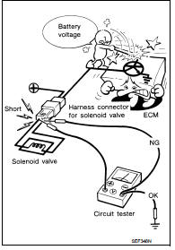
• When measuring ECM signals with a circuit tester, never allow the two tester probes to contact.
Accidental contact of probes will cause a short circuit and damage the ECM power transistor.
• Do not operate fuel pump when there is no fuel in lines.
• Tighten fuel hose clamps to the specified torque.
• Do not depress accelerator pedal when starting.
• Immediately after starting, do not rev up engine unnecessarily.
• Do not rev up engine just prior to shutdown.
• When installing C.B. ham radio or a mobile phone, be sure to observe the following as it may adversely affect electronic control systems depending on installation location.
- Keep the antenna as far as possible from the electronic control units.
- Keep the antenna feeder line more than 20 cm (8 in) away from the harness of electronic controls. Do not let them run parallel for a long distance.
- Adjust the antenna and feeder line so that the standing-wave ratio can be kept smaller.
- Be sure to ground the radio to vehicle body.
 On Board Diagnostic (OBD) System of Engine and CVT
The ECM has an on board diagnostic system. It will light up the malfunction
indicator lamp (MIL) to warn the
driver of a malfunction causing emission deterioration.
CAUTION:
• Be sure to turn ...
 Preparation
...
Other materials:
Washing
Wash dirt off the vehicle with a wet sponge and plenty of water. Clean the vehicle
thoroughly using a mild soap, a special vehicle soap or general purpose dishwashing
liquid mixed with clean, lukewarm (never hot) water.
CAUTION
• Do not use car washes that use acid in the detergent. Some car ...
Evaporative emission system
Inspection
1. Visually inspect EVAP vapor lines for improper attachment and for cracks,
damage, loose connections,
chafing and deterioration.
2. Check EVAP canister as follows:
a. Block port (B). Orally blow air through port (A).
Check that air flows freely through port (C).
b. Block port (A ...
Rear door lock
Exploded View
1. Outside handle assembly
2. Rear door sealing screen
3. Door lock assembly
4. TORX bolt
5. Inside handle
: Clip
: Pawl
: Vehicle front
: Do not reuse
: N·m (kg-m, in-lb)
: Body grease
Door lock
DOOR LOCK : Removal and Installation
REMOVAL
1. Remove rear door glas ...
