Nissan Juke Service and Repair Manual : G sensor
Exploded View
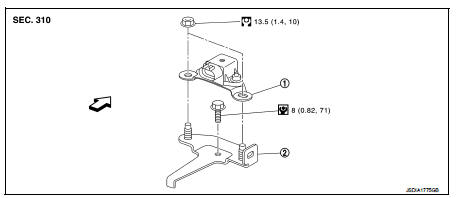
1. Bracket
2. G sensor
 : Vehicle front
 : N·m (kg-m, ft-lb)
 : N·m (kg-m, in-lb)
Removal and Installation
CAUTION:
• Never drop or strike G sensor, because it has little tolerance for impact.
• Never use a power tool to avoid impact.
REMOVAL
1. Disconnect the battery cable from the negative terminal. Refer to PG-124, "Removal and Installation".
2. Remove driver seat (LHD) or passenger seat (RHD). Refer to SE-19, "Removal and Installation".
3. Remove center pillar lower garnish (left side) and dash side finisher (left side). Refer to INT-20, "CENTER PILLAR LOWER GARNISH : Removal and Installation" (center pillar lower garnish) and INT-20, "DASH SIDE FINISHER : Removal and Installation" (dash side finisher).
4. Pull up floor carpet. Refer to INT-23, "Removal and Installation".
5. Disconnect G sensor harness connector.
6. Remove G sensor.
7. Remove bracket.
INSTALLATION
Installation is the reverse order of removal.
Adjustment
ADJUSTMENT AFTER INSTALLATION
Perform “G SENSOR CALIBRATION”. Refer to TM-377, "Description".
 Air breather hose
Removal and Installation
REMOVAL
1. Remove clip from bracket.
2. Remove air breather hose from transaxle assembly.
INSTALLATION
Note the following, and install in the reverse order of removal.
...
 Oil pan
Exploded View
1. Transaxle assembly
2. Oil pan gasket
3. Magnet
4. Oil pan
5. Overflow tube
6. Drain plug gasket
7. Drain plug
8. Oil pan fitting bolt
: Always replace after every
di ...
Other materials:
P1616 ECM
DTC Logic
DTC DETECTION LOGIC
DTC CONFIRMATION PROCEDURE
1.PERFORM DTC CONFIRMATION PROCEDURE FOR MALFUNCTION
1. Turn ignition switch ON amd wait 2 seconds or more.
2. Check DTC in “Self Diagnostic Result” mode of “ENGINE” using CONSULT-III.
Is DTC detected?
YES >> Go to SEC ...
Diagnosis system (A/C auto AMP.)
Description
Air conditioning system performs self-diagnosis, operation check, function
diagnosis, and various settings
using diagnosis function of each control unit.
CONSULT-III Function
CONSULT-III performs the following functions via CAN communication with A/C
auto amp.
NOTE:
Diagnos ...
Integrated control system (if so equipped)
The Integrated Control System is located below the audio system or navigation
system (if so equipped). Two Integrated Control System modes can be selected: Drive
mode and Climate Control mode.
Depending on which Integrated Control System mode is selected (Drive mode or
Climate Control mode), ...
