Nissan Juke Service and Repair Manual : Ecu diagnosis information
NAVI CONTROL UNIT
Reference Value
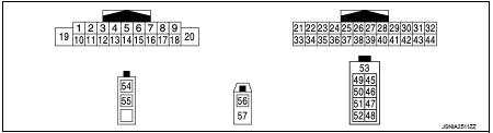
TERMINAL LAYOUT
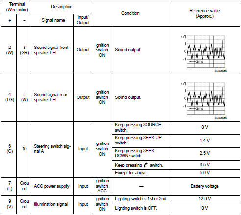
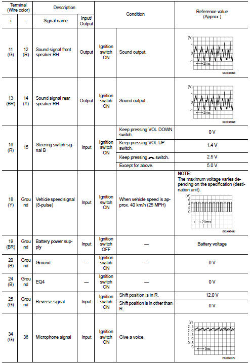
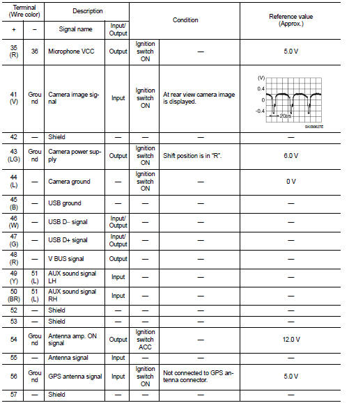
PHYSICAL VALUES
 Diagnosis system (navi control unit)
Diagnosis Description
On-Board Diagnosis Item
• On-board diagnosis is performed in service test mode.
• On-board diagnosis checks if the system operates normally.
Service test mode
METH ...
 Wiring diagram
AUDIO WITH NAVIGATION
Wiring Diagram
For connector terminal arrangements, harness layouts, and alphabets in a
(option abbreviation; if not
described in wiring diagram), refer to GI-12, "Conne ...
Other materials:
Continuously Variable Transmission (CVT)
The ignition lock is designed so that the ignition switch cannot be turned to
the LOCK position until the shift lever is moved to the P (Park) position.
• When turning the ignition switch to the LOCK position, make sure that the shift
lever is in the P (Park) position.
• When removing th ...
Li-ion battery warmer
For models equipped with a 40 kWh battery
CAUTION
The Li-ion battery warmer system is designed to maintain optimal battery health; however, it will not operate if the available battery charge is approximately 15% or less and the vehicle is not connected to a charging source. To protect the ...
G sensor
Exploded View
1. G sensor
: Vehicle front
: N·m (kg-m, in-lb)
Removal and Installation
CAUTION:
• Never drop or strike G sensor, because it has little tolerance for impact.
• Never use a power tool to avoid impact.
REMOVAL
1. Disconnect the battery cable from the negative terminal. R ...
