Nissan Juke Service and Repair Manual : Diagnosis and repair workflow
Gasoline engine models
GASOLINE ENGINE MODELS : Work Flow
OVERALL SEQUENCE
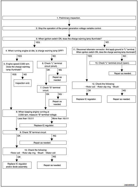
DETAILED FLOW
1.PRELIMINARY INSPECTION
Perform the preliminary inspection. Refer to CHG-17, "Inspection Procedure".
Models with battery current sensor>>GO TO 2.
Models without battery current sensor>>GO TO 3.
2.STOP POWER GENERATION VOLTAGE VARIABLE CONTROL SYSTEM
Stop the operation of the power generation voltage variable control in either of the following procedures.
ŌĆó After selecting ŌĆ£ENGINEŌĆØ of ŌĆ£SELECT SYSTEMŌĆØ using CONSULT-III, set the DUTY value of ŌĆ£ALTERNATOR DUTYŌĆØ to 0 % by selecting ŌĆ£ALTERNATOR DUTYŌĆØ of ŌĆ£Active TestŌĆØ. Continue ŌĆ£Active TestŌĆØ until the end of inspection. (When the DUTY value is 0 or 100 %, the normal power generation is performed according to the characteristic of the IC regulator of the alternator.) ŌĆó Turn the ignition switch OFF, and disconnect the battery current sensor connector. [However, DTC (P1550 - P1554) of the engine might remain. After finishing the inspection, connect the battery current sensor connector and erase the self-diagnostic results history of the engine using CONSULT-III.] >> GO TO 3.
3.INSPECTION WITH CHARGE WARNING LAMP (IGNITION SWITCH IS ON)
Turn the ignition switch ON.
Does the charge warning lamp illuminate? YES >> GO TO 4.
NO >> GO TO 11.
4.INSPECTION WITH CHARGE WARNING LAMP (IDLING)
Start the engine and run it at idle.
Does the charge warning lamp turn OFF? YES >> GO TO 5.
NO >> GO TO 6.
5.INSPECTION WITH CHARGE WARNING LAMP
Increase and maintain the engine speed at 2,500 rpm.
Does the charge warning lamp illuminate? YES >> GO TO 8.
NO >> INSPECTION END
6.ŌĆ£LŌĆØ TERMINAL CIRCUIT (SHORT) INSPECTION
Check ŌĆ£LŌĆØ terminal circuit (short). Refer to CHG-23, "Diagnosis Procedure".
Is the inspection result normal? YES >> GO TO 7.
NO >> Repair as needed.
7.ŌĆ£SŌĆØ TERMINAL CIRCUIT INSPECTION
Check ŌĆ£SŌĆØ terminal circuit. Refer to CHG-24, "Diagnosis Procedure".
Is the inspection result normal? YES >> GO TO 8.
NO >> Repair as needed.
8.MEASURE ŌĆ£BŌĆØ TERMINAL VOLTAGE
Start engine. When keeping engine running at 2,500 rpm, measure ŌĆ£BŌĆØ terminal voltage.
What voltage does the measurement result show? Less than 13.0 V>>GO TO 9.
More than 16.0 V>>Replace IC voltage regulator.
9.ŌĆ£BŌĆØ TERMINAL CIRCUIT INSPECTION
Check ŌĆ£BŌĆØ terminal circuit. Refer to CHG-20, "Diagnosis Procedure".
Is the inspection result normal? YES >> GO TO 10.
NO >> Repair as needed.
10.DISASSEMBLE AND CHECK ALTERNATOR
Check the following conditions.
ŌĆó Rotor coil
ŌĆó Rotor slip ring
ŌĆó Brush
ŌĆó Stator coil
Refer to CHG-29, "HR16DE : Inspection" (HR16DE), CHG-33, "MR16DDT : Inspection" (MR16DDT).
Are these normal? YES >> Replace IC voltage regulator and/or diode assembly.
NO >> Repair as needed.
11.INSPECTION WITH CHARGE WARNING LAMP (IGNITION SWITCH IS ON)
1. Disconnect alternator connector and ground ŌĆ£LŌĆØ harness side.
2. Turn the ignition switch ON.
Does the charge warning lamp illuminate? YES >> GO TO 12.
NO >> GO TO 13.
12.DISASSEMBLE AND CHECK ALTERNATOR
Check the following conditions.
ŌĆó Rotor coil
ŌĆó Rotor slip ring
ŌĆó Brush
Refer to CHG-29, "HR16DE : Inspection" (HR16DE), CHG-33, "MR16DDT : Inspection" (MR16DDT).
Are these normal? YES >> Replace IC voltage regulator.
NO >> Repair as needed.
13.CHECK ŌĆ£LŌĆØ TERMINAL CIRCUIT (OPEN)
Check ŌĆ£LŌĆØ terminal circuit (open). Refer to CHG-21, "Diagnosis Procedure".
>> Repair as needed.
Diesel engine models
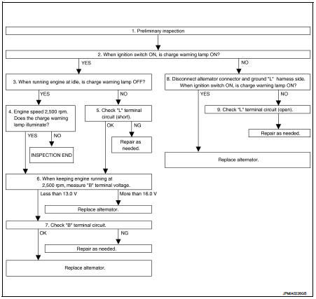
DIESEL ENGINE MODELS : Work Flow
OVERALL SEQUENCE
DETAILED FLOW
1.PRELIMINARY INSPECTION
Perform the preliminary inspection. Refer to CHG-17, "Inspection Procedure".
>> GO TO 2.
2.INSPECTION WITH CHARGE WARNING LAMP (IGNITION SWITCH IS ON)
Turn the ignition switch ON.
Does the charge warning lamp illuminate? YES >> GO TO 3.
NO >> GO TO 8.
3.INSPECTION WITH CHARGE WARNING LAMP (IDLING)
Start the engine and run it at idle.
Does the charge warning lamp turn OFF? YES >> GO TO 4.
NO >> GO TO 5.
4.INSPECTION WITH CHARGE WARNING LAMP (ENGINE AT 2,500 RPM)
Increase and maintain the engine speed at 2,500 rpm.
Does the charge warning lamp illuminate? YES >> GO TO 6.
NO >> INSPECTION END
5.ŌĆ£LŌĆØ TERMINAL CIRCUIT (SHORT) INSPECTION
Check ŌĆ£LŌĆØ terminal circuit (short). Refer to CHG-23, "Diagnosis Procedure".
Is the inspection result normal? YES >> GO TO 6.
NO >> Repair as needed.
6.MEASURE ŌĆ£BŌĆØ TERMINAL VOLTAGE
Engine start. When keeping engine running at 2,500 rpm, measure ŌĆ£BŌĆØ terminal voltage.
What voltage does the measurement result show? Less than 13.0 V>>GO TO 7.
More than 16.0 V>>Replace alternator.
7.ŌĆ£BŌĆØ TERMINAL CIRCUIT INSPECTION
Check ŌĆ£BŌĆØ terminal circuit. Refer to CHG-20, "Diagnosis Procedure".
Is the inspection result normal? YES >> Replace alternator.
NO >> Repair as needed.
8.INSPECTION WITH CHARGE WARNING LAMP (IGNITION SWITCH IS ON)
1. Disconnect alternator connector and ground ŌĆ£LŌĆØ harness side.
2. Turn the ignition switch ON.
Does the charge warning lamp illuminate? YES >> Replace alternator.
NO >> GO TO 9.
9.CHECK ŌĆ£LŌĆØ TERMINAL CIRCUIT (OPEN)
Check ŌĆ£LŌĆØ terminal circuit (open). Refer to CHG-21, "Diagnosis Procedure".
>> Repair as needed.
 Basic inspection
...
 Charging system preliminary inspection
Inspection Procedure
1.CHECK BATTERY TERMINALS CONNECTION
Check if battery terminals are clean and tight.
Is the inspection result normal?
YES >> GO TO 2.
NO >> Repair battery ter ...
Other materials:
Brake and clutch (if so equipped) fluid
For additional brake and clutch fluid information, see ŌĆ£Capacities and recommended
fuel/lubricantsŌĆØ of this manual.
WARNING
ŌĆó Use only new fluid from a sealed container. Old, inferior or contaminated
fluid may damage the brake and clutch systems. The use of improper fluids can dama ...
Service Equipment
RECOVERY/RECYCLING RECHARGING EQUIPMENT
Be certain to follow the manufacturerŌĆÖs instructions for machine operation
and machine maintenance. Never
introduce any refrigerant other than that specified into the machine.
ELECTRICAL LEAK DETECTOR
Be certain to follow the manufacturerŌĆÖs instruc ...
B2618 BCM
DTC Logic
DTC DETECTION LOGIC
NOTE:
ŌĆó If DTC B2618 is displayed with DTC U1000, first perform the trouble diagnosis
for DTC U1000. Refer to
BCS-83, "DTC Logic".
ŌĆó If DTC B2618 is displayed with DTC U1010, first perform the trouble diagnosis
for DTC U1010. Refer to
BCS-84, &qu ...
