Nissan Juke Service and Repair Manual : Diagnosis and repair work flow
Work Flow
OVERALL SEQUENCE
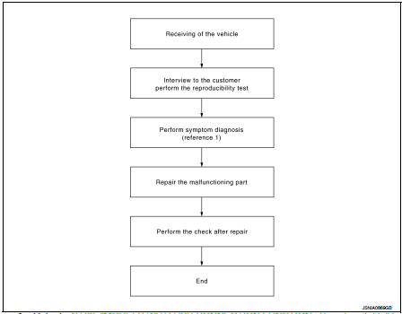
Reference 1··· Refer to AV-33, "MODELS WITH USB CONNECTION FUNCTION : Symptom Table" (with USB connection function) or AV-35, "MODELS WITHOUT USB CONNECTION FUNCTION : Symptom Table" (without USB connection function).
DETAILED FLOW
1.CHECK SYMPTOM
Check the malfunction symptoms by performing the following items.
• Interview the customer to obtain the malfunction information (conditions and environment when the malfunction occurred).
• Check the symptom.
>> GO TO 2.
2.PERFORM DIAGNOSIS BY SYMPTOM
Perform the relevant diagnosis referring to the diagnosis chart by symptom. Refer to AV-33, "MODELS WITH USB CONNECTION FUNCTION : Symptom Table" (with USB connection function) or AV-35, "MODELS WITHOUT USB CONNECTION FUNCTION : Symptom Table" (without USB connection function).
>> GO TO 3.
3.REPAIR OR REPLACE MALFUNCTIONING PARTS
Repair or replace the malfunctioning parts.
>> GO TO 4.
4.FINAL CHECK
Perform the operation to check that the malfunction symptom is solved or any other symptoms are present.
Is there any symptom? YES >> GO TO 2.
NO >> INSPECTION END
 Basic inspection
...
 Additional service when removing battery negative terminal
Description
• The audio unit is equipped with the anti-theft system.
• The audio unit operates after authenticating a fixed four-digit anti-theft
code.
• After removing the battery of the a ...
Other materials:
C1121, C1123, C1125, C1127 ABS out valve system
DTC Logic
DTC DETECTION LOGIC
DTC CONFIRMATION PROCEDURE
1.PRECONDITIONING
If “DTC CONFIRMATION PROCEDURE” has been previously conducted, always turn
ignition switch OFF and
wait at least 10 seconds before conducting the next test.
>> GO TO 2.
2.CHECK DTC DETECTION
With CON ...
P0137 HO2S2
DTC Logic
DTC DETECTION LOGIC
The heated oxygen sensor 2 has a much longer switching time
between rich and lean than the air fuel ratio (A/F) sensor 1. The oxygen
storage capacity of the three way catalyst 1 causes the longer
switching time. To judge the malfunctions of heated oxygen sensor
2, ...
Front fog lamp
Exploded View
1. Front fog lamp assembly
2. Metal clip
3. Front fog lamp bulb
4. Front fog lamp bracket
5. U nut
6. Front bumper fascia lower
: Pawl
: N·m (kg-m, in-lb)
Removal and Installation
CAUTION:
Disconnect the battery negative terminal or remove the fuse.
REMOVAL
1. Remov ...
