Nissan Juke Service and Repair Manual : CVT control system
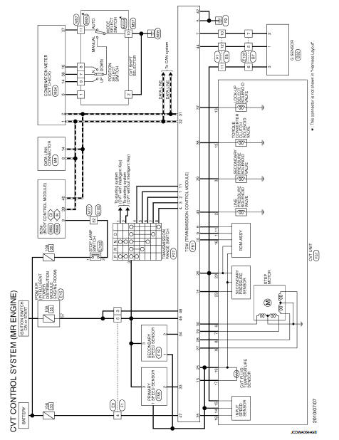
Wiring diagram
For connector terminal arrangements, harness layouts, and alphabets in a
 (option abbreviation; if
notdescribed
in wiring diagram), refer to GI-12, "Connector Information/Explanation of Option
Abbreviation".
 Wiring diagram
...
 CVT shift lock system
Wiring diagram
For connector terminal arrangements, harness layouts, and alphabets in a
(option abbreviation; if
notdescribed
in wiring diagram), refer to GI-12, "Connector Information/Expla ...
Other materials:
Turbocharger (If Equipped)
The turbocharger turbine revolves at extremely high speeds and
becomes very hot. Therefore, it is essential to maintain a clean supply
of oil flowing through the turbocharger and to follow all required
maintenance instructions and operating procedures.
• Always use the recommended oil. Follo ...
Engine idle speed too low or unstable
Description
CHART 6: ENGINE IDLE SPEED TOO LOW OR UNSTABLE
Diagnosis Procedure
1.CHECK FUEL
Check that the fuel reservoir is correctly filled and with the right fuel.
>> GO TO 2.
2.CHECK ECM POWER SUPPLY AND GROUND CIRCUIT
Check ECM power supply and ground circuit. Refer to EC-885, ...
Front wiper arm
Exploded View
RHD models
1. Front wiper arm cap
2. Front wiper arm RH
3. Front wiper drive assembly
4. Front wiper motor
5. Front wiper blade LH
6. Front wiper arm LH
7. Front wiper blade RH
: Pawl
: N·m (kg-m, in-lb)
: N·m (kg-m, ft-lb)
LHD models
1. Front wiper arm cap
2. ...
