Nissan Juke Service and Repair Manual : B2636, B2637, B2638, B2639, B2654, B2655 mode door motor
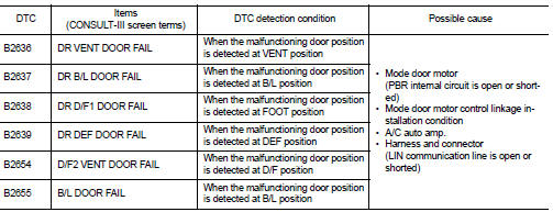
DTC Logic
DTC DETECTION LOGIC
DTC CONFIRMATION PROCEDURE
1.PERFORM DTC CONFIRMATION PROCEDURE
 With CONSULT-III
1. Turn ignition switch ON.
2. Select ŌĆ£Self Diagnostic ResultŌĆØ mode of ŌĆ£HVACŌĆØ using CONSULT-III.
3. Check DTC.
Is DTC detected? YES >> Refer to HAC-157, "Diagnosis Procedure".
NO >> INSPECTION END
Diagnosis Procedure
1.CHECK MODE DOOR MOTOR POWER SUPPLY
1. Turn ignition switch ON.
2. Check voltage between mode door motor harness connector and ground.
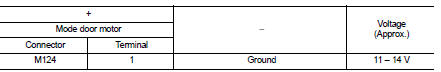
Is the inspection result normal? YES >> GO TO 2.
NO >> GO TO 5.
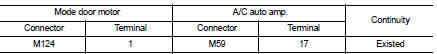
2.CHECK MODE DOOR MOTOR GROUND CIRCUIT FOR OPEN
1. Turn ignition switch OFF.
2. Disconnect mode door motor and A/C auto amp. connector.
3. Check continuity between mode door motor harness connector and A/C auto amp. harness connector.
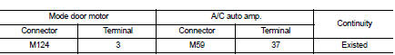
Is the inspection result normal? YES >> GO TO 3.
NO >> Repair harness or connector.
3.CHECK MODE DOOR MOTOR LIN SIGNAL
1. Connect mode door motor and A/C auto amp. connector.
2. Turn ignition switch ON.
3. Confirm output waveform between mode door motor harness connector and ground using oscilloscope.
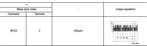
Is the inspection result normal? YES >> GO TO 4.
NO >> GO TO 6.
4.CHECK INSTALLATION OF MODE DOOR MOTOR
Check mode door motor is properly installed. Refer to HAC-195, "Exploded View".
Is the inspection result normal? YES >> Replace mode door motor. Refer to HAC-197, "MODE DOOR MOTOR : Removal and Installation".
NO >> Repair or replace malfunctioning part.
5.CHECK MODE DOOR MOTOR POWER SUPPLY CIRCUIT FOR OPEN
1. Turn ignition switch OFF.
2. Disconnect mode door motor and A/C auto amp. connector.
3. Check continuity between mode door motor harness connector and A/C auto amp. harness connector.
Is the inspection result normal? YES >> Replace A/C auto amp. Refer to HAC-188, "Removal and Installation".
NO >> Repair harness or connector.
6.CHECK MODE DOOR MOTOR LIN SIGNAL CIRCUIT FOR OPEN
1. Turn ignition switch OFF.
2. Disconnect mode door motor and A/C auto amp. connector.
3. Check continuity between mode door motor harness connector and A/C auto amp. harness connector.
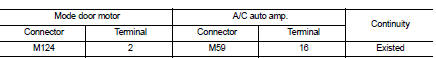
Is the inspection result normal? YES >> Replace A/C auto amp. Refer to HAC-188, "Removal and Installation".
NO >> Repair harness or connector.
 B2632, B2633 air mix door motor PBR
DTC Logic
DTC DETECTION LOGIC
DTC CONFIRMATION PROCEDURE
1.PERFORM DTC CONFIRMATION PROCEDURE
With CONSULT-III
1. Turn ignition switch ON.
2. Select ŌĆ£Self Diagnostic ResultŌĆØ mode of ŌĆ£HVA ...
 B263D, B263E, B263F intake door motor
DTC Logic
DTC DETECTION LOGIC
DTC CONFIRMATION PROCEDURE
1.PERFORM DTC CONFIRMATION PROCEDURE
With CONSULT-III
1. Turn ignition switch ON.
2. Select ŌĆ£Self Diagnostic ResultŌĆØ mode of ŌĆ£HVA ...
Other materials:
Speed limiter
Speed limiter : System Diagram
Speed limiter : System Description
INPUT/OUTPUT SIGNAL CHART
*: This signal is sent to the ECM through CAN communication line
BASIC SPEED LIMITER SYSTEM
ŌĆó Speed limiter is a system that enables to restrict the vehicle speed within
the set speed that is se ...
Unit disassembly and assembly
Torque converter and converter housing oil seal
Exploded View
1. Transaxle assembly
2. Converter housing oil seal
3. Torque converter
: Always replace after every
disassembly.
: Apply CVT Fluid NS-2.
Disassembly
1. Remove transaxle assembly. Refer to TM-301, "Removal and Installat ...
Ambient sensor
Removal and Installation
REMOVAL
1. Remove bumper fascia assembly. Refer to EXT-13, "Removal and
Installation".
2. Disengage fixing pawl, and then remove ambient sensor (1)
from air guide RH.
: Pawl
3. Disconnect ambient sensor connector (2), and then remove
ambient sensor.
INS ...
