Nissan Juke Service and Repair Manual : Water pump
Exploded View
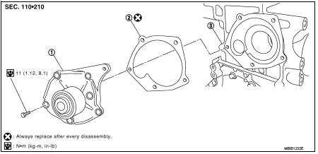
1. Water pump
2. Gasket
3. Cylinder block
Removal and Installation
WARNING:
Never remove the radiator cap when the engine is hot. Serious burns could occur
from high pressure
coolant escaping from the radiator.
REMOVAL
1. Drain engine coolant. Refer to CO-62, "Draining".
CAUTION:
Perform when engine is cold.
2. Remove front wheel RH.
3. Remove fender protector (RH). Refer to EXT-22, "Exploded View" 4. Remove drive belt. Refer to EM-276, "Removal and Installation".
5. Remove timing belt and inner cover. Refer to EM-302, "Exploded View".
6. Remove the water pump.
• Coolant will leak from the cylinder block, so have a receptacle ready below.
CAUTION:
• Handle the water pump vane so that it does not contact any other parts.
• Water pump cannot be disassembled and should be replaced as a unit.
INSTALLATION
• Install in the reverse order of removal.
Inspection
INSPECTION AFTER REMOVAL
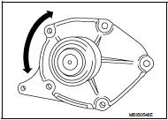
• Visually make sure there is no significant dirt or rusting on the water pump body and vane.
• Make sure there is no looseness in the vane shaft, and that it turns smoothly when rotated by hand.
• If there are any unusualness, replace the water pump assembly.
INSPECTION AFTER INSTALLATION
• Check for engine coolant leaks using reservoir tank cap tester. Refer to CO-62, "Inspection".
 Cooling fan
Exploded View
1. Fan motorCooling fan
2. Fan shroud
3. Cooling fan
A. Reverse screw
: Apply thread locking sealant.
: Vehicle front
: N·m (kg-m, in-lb)
Removal and Installation
REMOVAL
1 ...
 Thermo plunger unit
Exploded View
1. Side member LH
2. Thermo plunger control unit
3. Thermo plunger relay
4. Thermo plunger connector
5. Earth lead
6. Thermo plunger unit
7. Bracket stay
Vehicle front
: ...
Other materials:
Description
This vehicle has both new standard based on ISO* and previous standard
bolts/nuts. There are some differences
between these two types of bolts/ nuts; shape of the head, grade of strength,
hexagonal width across
flats and the standard tightening torque.
• For guidance in discriminating, refe ...
P1642 thermoplunger control unit
DTC Logic
DTC DETECTION LOGIC
Diagnosis Procedure
1.CHECK THERMOPLUNGER CONTROL UNIT POWER SUPPLY CIRCUIT
1. Turn ignition switch OFF.
2. Disconnect thermoplunger control unit harness connector.
3. Check the voltage between thermoplunger control unit harness connector and
ground.
Is the ...
Door does not lock/unlock with driver side door lock
knob or door key cylinder
Diagnosis Procedure
1.CHECK POWER DOOR LOCK OPERATION
Check power door lock operation.
Does door lock/unlock with door lock and unlock switch?
YES >> GO TO 2.
NO >> Go to DLK-534, "ALL DOOR : Diagnosis Procedure".
2.CHECK UNLOCK SENSOR
Check unlock sensor.
Refer ...
