Nissan Juke Service and Repair Manual : Cooling fan
Exploded View
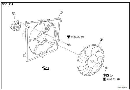
1. Fan motorCooling fan
2. Fan shroud
3. Cooling fan
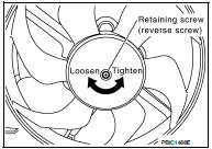
A. Reverse screw
 : Apply thread locking sealant.
 : Vehicle front
 : N·m (kg-m, in-lb)
Removal and Installation
REMOVAL
1. Drain engine coolant. Refer to CO-62, "Draining".
2. Disconnect radiator hose (lower) clip.
3. Remove battery. Refer to PG-124, "Exploded View" 4. Remove air duct (inlet). Refer to EM-280, "Exploded View".
5. Remove fusible link and relay box bracket, and put fusible link and relay box aside.
6. Remove reservoir tank.
7. Disconnect fan motor connector and boost pressure control valve harness connector, and put the connectors aside.
8. Remove boost pressure control valve assembly. Refer to EC-825, "TURBOCHARGER BOOST CONTROL : Vacuum Hose Drawing".
9. Remove radiator upper hose. Refer to CO-66, "Exploded View".
10. Remove radiator fan and shroud assembly.
11. Remove radiator fan reverse screw.
12. Remove fan motor from fan shroud.
INSTALLATION
Install in the reverse order of removal.
 Radiator
Exploded View
1. Reservoir tank cap
2. Reservoir tank
3. Clamp
4. Reservoir tank hose
5. Mounting rubber (upper)
6. Reservoir tank hose
7. Radiator
8. Mounting rubber (lower)
9. Drain ...
 Water pump
Exploded View
1. Water pump
2. Gasket
3. Cylinder block
Removal and Installation
WARNING:
Never remove the radiator cap when the engine is hot. Serious burns could occur
from high pressure ...
Other materials:
Draining
WARNING:
• Never remove radiator cap when engine is hot. Serious burns may occur from
high-pressure engine
coolant escaping from radiator.
• Wrap a thick cloth around the radiator cap. Slowly turn it a quarter of a turn
to release built-up pressure.
Then turn it all the way.
1. Remove eng ...
Hazard and buzzer reminder does not operate
Diagnosis Procedure
1.CHECK DTC WITH BCM AND COMBINATION METER
Check that DTC is not detected with BCM and combination meter.
Is the inspection result normal?
YES >> GO TO 2.
NO-1 >> Refer to BCS-67, "DTC Index". (BCM)
NO-2 >> Refer to MWI-36, "DTC Index&qu ...
P1650 thermoplunger control unit
DTC Logic
DTC DETECTION LOGIC
Diagnosis Procedure
1.CHECK THERMOPLUNGER CONTROL UNIT POWER SUPPLY CIRCUIT
1. Turn ignition switch OFF.
2. Disconnect thermoplunger control unit harness connector.
3. Check the voltage between thermoplunger control unit harness connector and
ground.
Is the ...
