Nissan Juke Service and Repair Manual : Water outlet
Exploded View
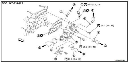
1. Engine coolant temperature sensor
2. Clamp
3. Gasket
4. Clamp
5. Bracket
6. Clamp
7. Water outlet
8. Clamp
9. Clamp
10. Washer
A. To electric throttle control actuator
B. To radiator
C. To CVT oil warmer
D. To heater core
E. To electric throttle control actuator
 : Engine front
 : Always replace after every
disassembly.
 : N·m (kg-m, ft-lb)
Removal and Installation
REMOVAL
1. Drain engine coolant from radiator. Refer to CO-37, "Draining".
CAUTION:
• Perform this step when engine is cold.
2. Remove air duct (inlet) and air ducts. Refer to EM-161, "Removal and Installation".
3. Disconnect radiator hose (upper). Refer to CO-42, "Exploded View".
4. Disconnect harness connector from engine coolant temperature sensor.
5. Remove water hoses and heater hoses.
6. Remove water outlet.
7. Remove engine coolant temperature sensor from water outlet, if necessary.
INSTALLATION
Installation is the reverse order of removal.
Inspection
INSPECTION AFTER REMOVAL
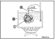
Water Control Valve
• Place a thread (A) so that it is caught in the valves of water control valve (1). Immerse fully in a container (B) filled with water. Heat while stirring.
• The valve opening temperature is the temperature at which the valve opens and falls from the thread.
• Continue heating. Check the continuous valve lifting toward maximum valve lift.
NOTE
:
The maximum valve lift amount standard temperature for water
control valve is the reference value.
• After checking the maximum valve lift amount, lower the water temperature and check the valve closing temperature.
Standard: Refer to CO-54, "Water Control Valve".
• If out of the standard, replace water control valve.
INSPECTION AFTER INSTALLATION
• Check for leakage of engine coolant using the radiator cap tester adapter (commercial service tool) and the radiator cap tester (commercial service tool). Refer to CO-37, "Inspection".
• Start and warm up the engine. Check visually that there is no leakage of engine coolant.
 Thermostat
Exploded View
1. Radiator hose (upper)
2. Water inlet
3. Rubber ring
4. Thermostat
A. To radiator
: Always replace after every
disassembly.
: N·m (kg-m, ft-lb)
Removal and Installation
...

Other materials:
Electrical load signal
Description
The electrical load signal (Headlamp switch signal, rear window defogger
switch signal, etc.) is transferred via
the CAN communication line.
Component Function Check
1.CHECK REAR WINDOW DEFOGGER SWITCH FUNCTION
With CONSULT-III
1. Turn ignition switch ON.
2. Select “DATA MONITOR ...
Coil spring
Exploded View
1. Upper rubber seat
2. Coil spring
3. Lower rubber seat
4. Suspension arm
: Vehicle front
Removal and Installation
REMOVAL
1. Remove tires. Refer to WT-7, "Removal and Installation".
2. Remove wheel sensor and sensor harness. Refer to BRC-86, "REAR WHEEL SE ...
Back door opener actuator
Component Function Check
1.CHECK FUNCTION
1. Select “INTELLIGENT KEY” of “BCM” using CONSULT-III.
2. Select “TRUNK/BACK DOOR” in “ACTIVE TEST” mode.
3. Check that the function operates normally according to the following
conditions.
Is the inspection result normal?
YES >> Back door o ...
