Nissan Juke Service and Repair Manual : Electrical load signal
Description
The electrical load signal (Headlamp switch signal, rear window defogger switch signal, etc.) is transferred via the CAN communication line.
Component Function Check
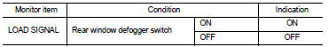
1.CHECK REAR WINDOW DEFOGGER SWITCH FUNCTION
 With CONSULT-III
1. Turn ignition switch ON.
2. Select “DATA MONITOR” mode of “ENGINE” using CONSULT-III.
3. Select “LOAD SIGNAL” and check indication as per the following conditions.
Is the inspection result normal? YES >> GO TO 2.
NO >> Proceed to EC-418, "Diagnosis Procedure".
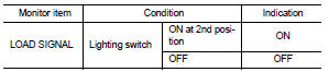
2.CHECK LIGHTING SWITCH FUNCTION
 With CONSULT-III
Check “LOAD SIGNAL” indication as per the following conditions.
Is the inspection result normal? YES >> GO TO 3.
NO >> Proceed to EC-418, "Diagnosis Procedure".
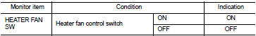
3.CHECK HEATER FAN CONTROL SWITCH FUNCTION
 With CONSULT-III
Select “HEATER FAN SW” and check indication as per the following conditions.
Is the inspection result normal? YES >> INSPECTION END
NO >> Proceed to EC-418, "Diagnosis Procedure".
Diagnosis Procedure
1.INSPECTION START
Confirm the malfunctioning circuit (rear window defogger, headlamp or heater fan). Refer to EC-418, "Component Function Check".
Which circuit is related to the incident? Rear window defogger>>GO TO 2.
Headlamp>>GO TO 3.
Heater fan>>GO TO 4.
2.CHECK REAR WINDOW DEFOGGER SYSTEM
Check the rear window defogger system. Refer to DEF-25, "Work Flow".
>> INSPECTION END 3.CHECK HEADLAMP SYSTEM
Check the headlamp system. Refer to EXL-43, "Work Flow".
>> INSPECTION END 4.CHECK HEATER FAN CONTROL SYSTEM
Check the heater fan control system. refer to HA-72, "Work Flow".
>> INSPECTION END
 Ignition signal
Component Function Check
1.INSPECTION START
Turn ignition switch OFF, and restart engine.
Does the engine start?
YES >> GO TO 2.
NO >> Proceed to EC-414, "Diagnosis Procedure ...
 Cooling fan
Component Function Check
1.CHECK COOLING FAN FUNCTION
With CONSULT-III
1. Turn ignition switch ON.
2. Perform “FAN DUTY CONTROL” in “ACTIVE TEST” mode of “ENGINE” using
CONSULT-III.
3. Check th ...
Other materials:
P0110 IAT sensor
DTC Logic
DTC DETECTION LOGIC
Diagnosis Procedure
1.CHECK GROUND CONNECTIONS
1. Turn ignition switch OFF.
2. Check ground connection E38. Refer to Ground inspection in GI-44, "Circuit
Inspection".
Is the inspection result normal?
YES >> GO TO 2.
NO >> Repair or ...
P0172 fuel injection system function
DTC Logic
DTC DETECTION LOGIC
With the Air/Fuel Mixture Ratio Self-Learning Control, the actual mixture
ratio can be brought closely to the
theoretical mixture ratio based on the mixture ratio feedback signal from the
A/F sensor 1. The ECM calculates
the necessary compensation to correct the ...
Avoiding collision and rollover
WARNING
Failure to operate this vehicle in a safe and prudent manner may result in
loss of control or an accident.
Be alert and drive defensively at all times. Obey all traffic regulations. Avoid
excessive speed, high speed cornering, or sudden steering maneuvers, because these
driving pract ...
