Nissan Juke Service and Repair Manual : Ignition signal
Component Function Check
1.INSPECTION START
Turn ignition switch OFF, and restart engine.
Does the engine start? YES >> GO TO 2.
NO >> Proceed to EC-414, "Diagnosis Procedure".
2.IGNITION SIGNAL FUNCTION
 With CONSULT-III
1. Perform “POWER BALANCE” in “ACTIVE TEST” mode of “ENGINE” using CONSULT-III.
2. Check that each circuit produces a momentary engine speed drop.
 Without CONSULT-III
1. Let engine idle.
2. Check the voltage signal between ECM harness connector and ground with an oscilloscope.
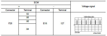
NOTE
:
The pulse cycle changes depending on rpm at idle.
Is the inspection result normal? YES >> INSPECTION END
NO >> Proceed to EC-414, "Diagnosis Procedure".
Diagnosis Procedure
1.CHECK CONDENSER POWER SUPPLY
1. Turn ignition switch OFF.
2. Disconnect condenser harness connector.
3. Turn ignition switch ON.
4. Check the voltage between condenser harness connector and ground.
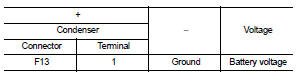
Is the inspection result normal? YES >> GO TO 3.
NO >> GO TO 2.
2.CHECK CONDENSER POWER SUPPLY CIRCUIT
1. Turn ignition switch OFF.
2. Disconnect IPDM E/R harness connector.
3. Check the continuity between IPDM E/R harness connector and condenser harness connector.
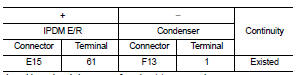
4. Also check harness for short to ground.
Is the inspection result normal? YES >> Perform the trouble diagnosis for power supply circuit.
NO >> Repair or replace error-detected parts.
3.CHECK CONDENSER GROUND CIRCUIT
1. Turn ignition switch OFF.
2. Check the continuity between Condenser harness connector and ground.
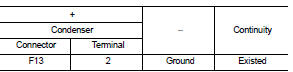
3. Also check harness for short to power.
Is the inspection result normal? YES >> GO TO 4.
NO >> Repair or replace error-detected parts.
4.CHECK CONDENSER
Check the condenser. refer to EC-417, "Component Inspection (Condenser)".
Is the inspection result normal? YES >> GO TO 5.
NO >> Replace condenser.
5.CHECK IGNITION COIL POWER SUPPLY
1. Reconnect all harness connectors disconnected.
2. Disconnect ignition coil harness connector.
3. Turn ignition switch ON.
4. Check the voltage between ignition coil harness connector and ground.
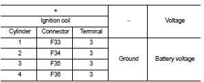
Is the inspection result normal? YES >> GO TO 6.
NO >> Perform the trouble diagnosis for power supply circuit.
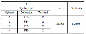
6.CHECK IGNITION COIL GROUND CIRCUIT
1. Turn ignition switch OFF.
2. Check the continuity between ignition coil harness connector and ground.
3. Also check harness for short to power.
Is the inspection result normal? YES >> GO TO 7.
NO >> Repair or replace error-detected parts.
7.CHECK IGNITION COIL OUTPUT SIGNAL CIRCUIT
1. Disconnect ECM harness connector.
2. Check the continuity between ECM harness connector and ignition coil harness connector.
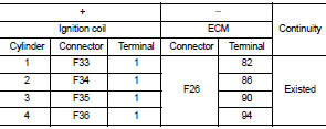
3. Also check harness for short to ground and short to power.
Is the inspection result normal? YES >> GO TO 8.
NO >> Repair or replace error-detected parts.
8.CHECK IGNITION COIL WITH POWER TRANSISTOR
Check the ignition coil with power transistor. Refer to EC-416, "Component Inspection (Ignition Coil with Power Transistor)".
Is the inspection result normal? YES >> Check intermittent incident. Refer to GI-42, "Intermittent Incident".
NO >> Replace malfunctioning ignition coil with power transistor. Refer to EM-53, "Exploded View".
Component Inspection (Ignition Coil with Power Transistor)
1.CHECK IGNITION COIL WITH POWER TRANSISTOR-I
1. Turn ignition switch OFF.
2. Disconnect ignition coil harness connector.
3. Check resistance between ignition coil terminals as per the following.
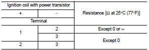
Is the inspection result normal? YES >> GO TO 2.
NO >> Replace malfunctioning ignition coil with power transistor. Refer to EM-53, "Exploded View".
2.CHECK IGNITION COIL WITH POWER TRANSISTOR-II
CAUTION:
Do the following procedure in the place where ventilation is good without the
combustible.
1. Turn ignition switch OFF.
2. Reconnect all harness connectors disconnected.
3. Remove fuel pump fuse in IPDM E/R to release fuel pressure.
NOTE
:
Do not use CONSULT-III to release fuel pressure, or fuel pressure applies again
during the following procedure.
4. Start engine.
5. After engine stalls, crank it two or three times to release all fuel pressure.
6. Turn ignition switch OFF.
7. Remove all ignition coil harness connectors to avoid the electrical discharge from the ignition coils. Refer to EM-53, "Exploded View".
8. Remove ignition coil and spark plug of the cylinder to be checked. Refer to .0EM-53, "Exploded View" 9. Crank engine for 5 seconds or more to remove combustion gas in the cylinder.
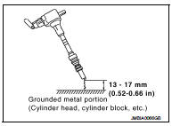
10. Connect spark plug and harness connector to ignition coil.
11. Fix ignition coil using a rope etc. with gap of 13 - 17 mm (0.52 - 0.66 in) between the edge of the spark plug and grounded metal portion as shown in the figure.
12. Crank engine for about three seconds, and check whether spark is generated between the spark plug and the grounded metal portion.
Spark should be generated.
CAUTION:
• During the operation, always stay 0.5 cm (19.7 in) away
from the spark plug and the ignition coil. Be careful not to
get an electrical shock while checking, because the electrical
discharge voltage becomes 20 kV or more.
• It might cause to damage the ignition coil if the gap of more than 17 mm (0.66 in) is taken.
NOTE:
When the gap is less than 13 mm (0.52 in), the spark might be generated even if
the coil is malfunctioning
Is the inspection result normal? YES >> INSPECTION END NO >> Replace malfunctioning ignition coil with power transistor. Refer to EM-53, "Exploded View".
Component Inspection (Condenser)
1.CHECK CONDENSER
1. Turn ignition switch OFF.
2. Disconnect condenser harness connector.
3. Check resistance between condenser terminals as per the following.
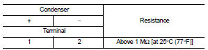
Is the inspection result normal? YES >> INSPECTION END
NO >> Replace Condenser.
 High pressure fuel pump
Component Function Check
1.CHECK HIGH PRESSURE FUEL PUMP FUNCTION
With CONSULT-III
1. Start engine.
2. Check “FUEL PRES SEN V” in “DATA MONITOR” mode of “ENGINE” using CONSULT-III.
Without CON ...
 Electrical load signal
Description
The electrical load signal (Headlamp switch signal, rear window defogger
switch signal, etc.) is transferred via
the CAN communication line.
Component Function Check
1.CHECK REAR WIN ...
Other materials:
Periodic maintenance
STEERING WHEEL
Inspection
STEERING WHEEL AXIAL END PLAY
1. Check installation conditions of steering gear assembly, front suspension
assembly, axle and steering column
assembly.
2. Check if movement exists when steering wheel is moved up and down, to the
left and right and to the axial
dir ...
Precaution
Precautions for Suspension
• When installing rubber bushings, the final tightening must be carried out
under unladen conditions with tires
on ground. Spilled oil might shorten the life of rubber bushings. Be sure to
wipe off any spilled oil.
- Unladen conditions mean that fuel, engine coolant ...
System (intelligent key system)
Intelligent key system : System Diagram
Intelligent key system : System Description
• The Intelligent Key system is a system that makes it possible to lock and
unlock the door locks (door lock/
unlock function) by carrying the Intelligent Key, which operates based on the
results of electron ...
