Nissan Juke Service and Repair Manual : P0172 fuel injection system function
DTC Logic
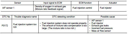
DTC DETECTION LOGIC
With the Air/Fuel Mixture Ratio Self-Learning Control, the actual mixture ratio can be brought closely to the theoretical mixture ratio based on the mixture ratio feedback signal from the A/F sensor 1. The ECM calculates the necessary compensation to correct the offset between the actual and the theoretical ratios.
In case the amount of the compensation value is extremely large (The actual mixture ratio is too rich.), the ECM judges the condition as the fuel injection system malfunction and lights up the MI (2 trip detection logic).
DTC CONFIRMATION PROCEDURE
1.PRECONDITIONING
If DTC Confirmation Procedure has been previously conducted, always turn ignition switch OFF and wait at least 10 seconds before conducting the next test.
>> GO TO 2.
2.PERFORM DTC CONFIRMATION PROCEDURE-I
1. Clear the mixture ratio self-learning value. Refer to EC-546, "Work Procedure".
2. Start engine.
Is it difficult to start engine? YES >> GO TO 3.
NO >> GO TO 4.
3.RESTART ENGINE
If it is difficult to start engine, the fuel injection system has a malfunction, too.
Crank engine while depressing accelerator pedal.
NOTE
:
When depressing accelerator pedal three-fourths (3/4) or more, the control
system may not start the engine.
Do not depress accelerator pedal too much.
Does engine start? YES >> Go to EC-640, "Diagnosis Procedure".
NO >> Remove spark plugs and check for fouling, etc.
4.PERFORM DTC CONFIRMATION PROCEDURE-II
1. Start engine and let it idle for at least 10 minutes.
2. Check 1st trip DTC.
Is 1st trip DTC detected? YES >> Go to EC-640, "Diagnosis Procedure".
NO >> GO TO 5.
5.PERFORM DTC CONFIRMATION PROCEDURE-III
1. Turn ignition switch OFF and wait at least 10 seconds.
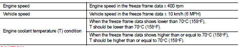
2. Start engine and drive the vehicle under the similar conditions to (1st trip) Freeze Frame Data for 10 minutes.
Refer to the table below.
Hold the accelerator pedal as steady as possible.
The similar conditions to (1st trip) Freeze Frame Data means the vehicle operation that the following conditions should be satisfied at the same time.
CAUTION:
Always drive at a safe speed.
3. Check 1st trip DTC.
Is 1st trip DTC detected? YES >> Go to EC-640, "Diagnosis Procedure".
NO >> INSPECTION END
Diagnosis Procedure
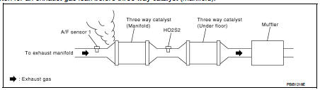
1.CHECK EXHAUST GAS LEAK
1. Start engine and run it at idle.
2. Listen for an exhaust gas leak before three way catalyst (manifold).
Is exhaust gas leak detected? YES >> Repair or replace.
NO >> GO TO 2.
2.CHECK FOR INTAKE AIR LEAK
Listen for an intake air leak after the mass air flow sensor.
Is intake air leak detected? YES >> Repair or replace.
NO >> GO TO 3.
3.CHECK A/F SENSOR 1 INPUT SIGNAL CIRCUIT FOR OPEN AND SHORT
1. Turn ignition switch OFF.
2. Disconnect corresponding A/F sensor 1 harness connector.
3. Disconnect ECM harness connector.
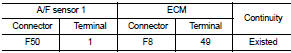
4. Check the continuity between A/F sensor 1 harness connector and ECM harness connector.
5. Check the continuity between A/F sensor 1 harness connector or ECM harness connector and ground.
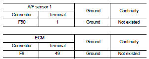
6. Also check harness for short to power.
Is the inspection result normal? YES >> GO TO 4.
NO >> Repair open circuit or short to ground or short to power in harness or connectors.
4.CHECK FUEL PRESSURE
1. Release fuel pressure to zero. Refer to EC-551, "Work Procedure".
2. Install fuel pressure gauge and check fuel pressure. Refer to EC-551, "Work Procedure".
At idling: Approximately 350 kPa (3.5 bar, 3.57 kg/cm2, 51 psi)
Is the inspection result normal? YES >> GO TO 6.
NO >> GO TO 5.
5. CHECK FUEL HOSES AND FUEL TUBES
Check fuel hoses and fuel tubes for clogging.
Is the inspection result normal? YES >> Replace “fuel filter and fuel pump assembly”.
NO >> Repair or replace 6.CHECK MASS AIR FLOW SENSOR
 With CONSULT-III
1. Install all removed parts.
2. Check “MASS AIRFLOW” in “DATA MONITOR” mode with CONSULT-III.
1.0 - 4.0 g·m/sec: at idling 2.0 - 10.0 g·m/sec: at 2,500 rpm
 With GST
1. Install all removed parts.
2. Check mass air flow sensor signal in “Service $01” with GST.
1.0 - 4.0 g·m/sec: at idling 2.0 - 10.0 g·m/sec: at 2,500 rpm
Is the measurement value within the specification? YES >> GO TO 7.
NO >> Check connectors for rusted terminals or loose connections in the mass air flow sensor circuit or grounds. Refer to EC-588, "DTC Logic".
7.CHECK FUNCTION OF FUEL INJECTOR
 With CONSULT-III
1. Start engine.
2. Perform “POWER BALANCE” in “ACTIVE TEST” mode with CONSULT-III.
3. Make sure that each circuit produces a momentary engine speed drop.
 Without CONSULT-III
1. Let engine idle.
2. Listen to each fuel injector operating sound.
Clicking noise should be heard.
Is the inspection result normal? YES >> GO TO 8.
NO >> Perform trouble diagnosis for FUEL INJECTOR. Refer to EC-778, "Component Function Check".
8.CHECK FUELINJECTOR
1. Remove fuel injector assembly. Refer to EM-173, "Exploded View".
Keep fuel hose and all fuel injectors connected to fuel tube.
2. Confirm that the engine is cooled down and there are no fire hazards near the vehicle.
3. Disconnect all fuel injector harness connectors.
4. Disconnect all ignition coil harness connectors.
5. Prepare pans or saucers under each fuel injectors.
6. Crank engine for about 3 seconds.
Make sure fuel does not drip from fuel injector.
Is the inspection result normal? YES >> GO TO 9.
NO >> Replace the fuel injectors from which fuel is dripping. Always replace O-ring with new one.
9.CHECK INTERMITTENT INCIDENT
Refer to GI-42, "Intermittent Incident".
>> INSPECTION END
 P0171 fuel injection system function
DTC Logic
DTC DETECTION LOGIC
With the Air/Fuel Mixture Ratio Self-Learning Control, the actual mixture
ratio can be brought closely to the
theoretical mixture ratio based on the mixture ratio fe ...
 P0197, P0198 EOT sensor
DTC Logic
DTC DETECTION LOGIC
DTC CONFIRMATION PROCEDURE
1.PRECONDITIONING
If DTC Confirmation Procedure has been previously conducted, always perform
the following procedure
before conductin ...
Other materials:
Brake master cyl
Exploded View
2WD
1. Reservoir cap
2. Oil strainer
3. Reservoir tank
4. Cylinder body
5. Pin
6. O-ring
7. Grommet
: Apply polyglycol ether based
lubricant.
: Apply brake fluid.
: N·m (kg-m, ft-lb)
: Always replace after every
disassembly.
4WD
1. Reservoir cap
2. Oil strai ...
Engine control system
Engine control system : Component Parts Location
ENGINE ROOM COMPARTMENT
1. Boost control actuator
2. Turbocharger boost control solenoid
valve
3. A/F sensor 1
4. Recirculation valve
5. EVAP canister purge volume control
solenoid valve
6. Inter cooler
7. Refrigerant pressure sensor
R ...
Removal and installation
IPDM E/R
Exploded View
1. IPDM E/R cover A
2. IPDM E/R
3. IPDM E/R cover B
Removal and Installation
IPDM E/R integrated relays are not serviceable parts, and must not be removed
from the unit.
REMOVAL
1. Remove battery.
2. Press and expand pawls (A) on lateral side of IPDM E/R cover ...
