Nissan Juke Service and Repair Manual : Coil spring
Exploded View
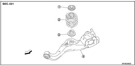
1. Upper rubber seat
2. Coil spring
3. Lower rubber seat
4. Suspension arm
 : Vehicle front
Removal and Installation
REMOVAL
1. Remove tires. Refer to WT-7, "Removal and Installation".
2. Remove wheel sensor and sensor harness. Refer to BRC-86, "REAR WHEEL SENSOR : Removal and Installation" (Without ESP), BRC-227, "REAR WHEEL SENSOR : Removal and Installation" (With ESP).
3. Set jack under suspension arm.
CAUTION:
• Never damage the suspension arm with a jack.
• Check the stable condition when using a jack.
4. Separate rear shock absorber lower side form suspension arm. Refer to RSU-8, "Removal and Installation".
5. Separate upper link from suspension arm.
6. Slowly lower jack, then remove upper rubber seat, coil spring and lower rubber seat from suspension arm.
CAUTION:
Operate while checking that jack supporting status is stable.
7. Perform inspection after removal. Refer to RSU-27, "Inspection" INSTALLATION
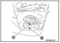
Note the following, and install in the reverse order of removal.
• Install the lower rubber seat a projection (A) is attached as suspension arm mounting hole (B).
• Match up lower rubber seat indentions and suspension arm grooves and attach.
• Perform inspection after installation. Refer to RSU-27, "Inspection".
Inspection
INSPECTION AFTER REMOVAL
Check lubber seat and coil spring for deformation, crack, and damage. Replace it if necessary.
INSPECTION AFTER INSTALLATION
1. Check wheel sensor harness for proper connection. Refer toBRC-85, "REAR WHEEL SENSOR : Exploded View" (Without ESP), BRC-225, "REAR WHEEL SENSOR : Exploded View" (With ESP).
2. Check wheel alignment. Refer to RSU-20, "Inspection".
 Rear shock absorber
Exploded View
1. Suspension arm
2. Shock absorber
3. Bound bumper
4. Bound bumper cover
5. Washer
6. Bushing
7. Distance tube
8. Piston rod lock nut
9. Cap
: Vehicle front
: Always r ...
 Suspension arm
Exploded View
1. Rear suspension member
2. Adjusting bolt
3. Upper link
4. Eccentric disk
5. Lower link
6. Suspension arm bracket
7. Suspension arm
: Vehicle front
: Always replace afte ...
Other materials:
Wiring diagram
DOOR & LOCK SYSTEM
Wiring Diagram
For connector terminal arrangements, harness layouts, and alphabets in a
(option abbreviation; if not
described in wiring diagram), refer to GI-12, "Connector Information/Explanation
of Option Abbreviation".
...
Does not operate
Description
ABS function and EBD function does not operate.
Diagnosis Procedure
CAUTION:
ABS function and EBD function never operate when the vehicle speed is 10 km/h
(6.2 MPH) or less.
1.CHECK ABS WARNING LAMP
Check that ABS warning lamp and brake warning lamp turn ON and turn OFF
appro ...
Precaution for Disposal
• Before disposing of air bag module, pop-up roll bar and seat belt pre-tensioner,
or vehicles equipped with
such systems, deploy the systems. If such systems have already been deployed due
to an accident, dispose
of them as indicated in Disposing of Air Bag Module, Pop-up Roll Bar and Seat
...
