Nissan Juke Service and Repair Manual : Suspension arm
Exploded View
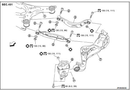
1. Rear suspension member
2. Adjusting bolt
3. Upper link
4. Eccentric disk
5. Lower link
6. Suspension arm bracket
7. Suspension arm
 : Vehicle front
 : Always replace after every
disassembly.
 : N·m (kg-m, ft-lb)
Removal and Installation
REMOVAL
1. Remove tires. Refer to WT-7, "Removal and Installation".
2. Drain brake fluid. Refer to BR-12, "Draining" (LHD), BR-80, "Draining" (RHD).
3. Remove wheel sensor and sensor harness. Refer to BRC-86, "REAR WHEEL SENSOR : Removal and Installation" (Without ESP), BRC-227, "REAR WHEEL SENSOR : Removal and Installation" (With ESP).
4. Remove caliper assembly. Refer to BR-65, "BRAKE CALIPER ASSEMBLY : Removal and Installation" (LHD), BR-131, "BRAKE CALIPER ASSEMBLY : Removal and Installation" (RHD).
5. Remove disc rotor. Refer to RAX-14, "Removal and Installation".
6. Remove parking brake cable mounting bolt. Refer to PB-5, "Removal and Installation".
7. Separate the brake tube from the brake hose, and remove lock plate. Refer to BR-30, "REAR : Exploded View" (LHD), BR-97, "REAR : Exploded View" (RHD).
8. Remove wheel hub assembly. Refer to RAX-14, "Removal and Installation".
9. Remove parking brake shoe and back plate. Refer to RAX-14, "Removal and Installation".
10. Set jack under suspension arm.
CAUTION
:
• Never damage the suspension arm with a jack.
• Check the stable condition when using a jack.
11. Remove stabilizer link. Refer to RSU-34, "Removal and Installation".
12. Remove upper link from suspension arm. Refer to RSU-32, "Removal and Installation".
13. Remove lower link from suspension arm. Refer to RSU-30, "Removal and Installation".
14. Remove coil spring from suspension arm. Refer to RSU-26, "Removal and Installation".
15. Remove suspension arm bracket from vehicle.
16. Remove suspension arm from suspension arm bracket.
17. Perform inspection after removal. Refer to RSU-29, "Inspection".
INSTALLATION
Note the following, and install in the reverse order of removal.
• Perform final tightening of rear suspension member installation position (rubber bussing), under unladen conditions with tires on level ground.
• Never reuse suspension arm mounting nut.
• Perform inspection after installation. Refer to RSU-29, "Inspection".
Inspection
INSPECTION AFTER REMOVAL
Check suspension arm and bushing for deformation, cracks or damage. Replace it if necessary.
INSPECTION AFTER INSTALLATION
1. Check wheel sensor harness for proper connection. Refer toBRC-85, "REAR WHEEL SENSOR : Exploded View" (Without ESP), BRC-225, "REAR WHEEL SENSOR : Exploded View" (With ESP).
2. Adjust parking brake operation (stroke). Refer toPB-2, "Inspection and Adjustment".
3. Check wheel alignment. Refer to RSU-20, "Inspection".
4. Adjust neutral position of steering angle sensor. Refer to BRC-149, "Work Procedure". (With ESP)
 Coil spring
Exploded View
1. Upper rubber seat
2. Coil spring
3. Lower rubber seat
4. Suspension arm
: Vehicle front
Removal and Installation
REMOVAL
1. Remove tires. Refer to WT-7, "Removal and ...
 Lower link
Exploded View
1. Rear suspension member
2. Adjusting bolt
3. Upper link
4. Eccentric disk
5. Lower link
6. Suspension arm bracket
7. Suspension arm
: Vehicle front
: Always replace afte ...
Other materials:
Precaution Necessary for Steering Wheel Rotation after Battery Disconnect
NOTE:
• Before removing and installing any control units, first turn the ignition
switch to the LOCK position, then disconnect
both battery cables.
• After finishing work, confirm that all control unit connectors are connected
properly, then re-connect both
battery cables.
• Always use CONS ...
Engine maintenance (HR16DE)
Drive belt
DRIVE BELT : Checking
• Inspection should be done only when engine is cold or over 30
minutes after the engine is stopped.
1 : Alternator
2 : Water pump
3 : Crankshaft pulley
4 : A/C compressor
5 : Idler pulley
6 : Drive belt
• Visually check belts for wear, damage, and cracks ...
Impossible to shut off engine
Description
CHART 4: IMPOSSIBLE TO SHUT OFF ENGINE
Diagnosis Procedure
1.CHECK ECM POWER SUPPLY AND GROUND CIRCUIT
Check ECM power supply and ground circuit. Refer to EC-885, "Diagnosis
Procedure".
Is the inspection result normal?
YES >> GO TO 2.
NO >> Repair or re ...
