Nissan Juke Service and Repair Manual : Rear shock absorber
Exploded View
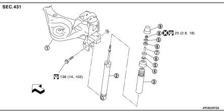
1. Suspension arm
2. Shock absorber
3. Bound bumper
4. Bound bumper cover
5. Washer
6. Bushing
7. Distance tube
8. Piston rod lock nut
9. Cap
 : Vehicle front
 : Always replace after every
disassembly.
 : N·m (kg-m, ft-lb)
Removal and Installation
REMOVAL
1. Remove tires. Refer to WT-7, "Removal and Installation".
2. Set suitable jack under suspension arm.
CAUTION:
• Never damage the suspension arm with a jack.
• Check the stable condition when using a jack.
3. Remove shock absorber mounting bolt and nut (lower side).
4. Remove shock absorber mask. Refer to INT-29, "Exploded View".
5. Remove cap.
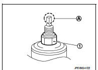
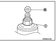
6. Remove piston rod lock nut (1), and then remove washer and bushing.
NOTE
:
To loosen piston rod lock nut, fix the tip (A) of the piston rod.
7. Remove shock absorber assembly.
8. Remove bushing, distance tube, bound bumper cover, and bound bumper from shock absorber.
9. Perform inspection after removal. Refer to RSU-24, "Inspection".
INSTALLATION
Note the following, and install in the reverse order of removal.
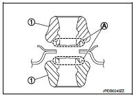
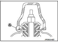
• To install bushings (1), securely insert protrusion (A) into the hole on the vehicle body side.
• Install washer (1) in the direction shown in the figure.
: Bushing side
• Perform final tightening of bolts and nuts at the shock absorber lower side (rubber bussing), under unladen conditions with tires on level ground.
• Hold a head (A) of shock absorber piston rod not to have it rotate, then tighten the piston rod lock nut (1) to the specified torque.
CAUTION:
Never reuse piston rod lock nut.
• When installing the cap, securely engage the cap groove (A) with the flange on the vehicle side.
• Perform inspection after installation. Refer to RSU-24, "Inspection".
• After replacing the shock absorber, always follow the disposal procedure to discard the shock absorber. Refer to RSU-24, "Inspection".
Inspection
INSPECTION AFTER REMOVAL
Shock Absorber
Check the following items, and replace the part if necessary.
• Shock absorber for deformation, cracks, and other damage.
• Piston rod for damage, uneven wear, and distortion.
• Oil leakage
Bound Bumper, Bushing Check for cracks and damage. Replace it if necessary.
Washer, Bound Bumper Cover, Distance Tube • Check for cracks and damage. Replace it if necessary.
INSPECTION AFTER INSTALLATION
Check wheel alignment. Refer to RSU-20, "Inspection".
Disposal
1. Set shock absorber horizontally to the ground with the piston rod fully extracted.
2. Drill 2 – 3 mm (0.08 – 0.12 in) hole at the position (
 ) from top
as shown in the figure to release gas gradually.
CAUTION:
• Wear eye protection (safety glass).
• Wear gloves.
• Be careful with metal chips or oil blown out by the compressed gas.
NOTE:
• Drill vertically in this direction (
 ).
).
• Directly to the outer tube avoiding brackets.
• The gas is clear, colorless, odorless, and harmless.
A : 20 – 30 mm (0.79 – 1.18 in)
3. Position the drilled hole downward and drain oil by moving the piston rod several times.
CAUTION:
Dispose of drained oil according to the law and local regulations.

 Coil spring
Exploded View
1. Upper rubber seat
2. Coil spring
3. Lower rubber seat
4. Suspension arm
: Vehicle front
Removal and Installation
REMOVAL
1. Remove tires. Refer to WT-7, "Removal and ...
Other materials:
B210E starter relay
DTC Logic
DTC DETECTION LOGIC
NOTE:
• If DTC B210E is displayed with DTC U1000, first perform the trouble diagnosis
for DTC U1000. Refer to
PCS-59, "DTC Logic".
• If DTC B210E is displayed with DTC B209F, first perform the trouble diagnosis
for DTC B209F. Refer to
SEC-209, " ...
Shift position indicator circuit
Component Parts Function Inspection
1.CHECK SHIFT POSITION INDICATOR
1. Start the engine.
2. Shift selector lever.
3. Check that the selector lever position and the shift position indicator on
the combination meter are identical.
Is the inspection result normal?
YES >> INSPECTION END ...
P range interlock door lock/unlock function does not operate
Diagnosis Procedure
1.CHECK “AUTOMATIC LOCK/UNLOCK SELECT” SETTING IN “WORK SUPPORT”
1. Select “DOOR LOCK” of “BCM” using CONSULT-III.
2. Select “AUTOMATIC LOCK/UNLOCK SELECT” in “WORK SUPPORT” mode.
3. Check “AUTOMATIC LOCK/UNLOCK SELECT” setting in “WORK SUPPORT”.
Refer to DLK-371, "DO ...
