Nissan Juke Service and Repair Manual : Thermo control amplifier
Component Function Check
1.CHECK A/C ON SIGNAL
 With CONSULT-III
1. Turn ignition switch ON.
2. Select “AIR CONDITIONER” of “BCM” using CONSULT-III.
3. Select “THERMO AMP” in “DATA MONITOR” mode, and check status under the following condition.
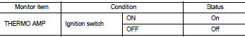
Is the inspection result normal? YES >> INSPECTION END
NO >> Refer to HAC-224, "Diagnosis Procedure".
Diagnosis Procedure
1.CHECK FUSE
1. Turn ignition switch OFF.
2. Check 10A fuse (No. 15, located in fuse block (J/B)].
NOTE
:
Refer to PG-22, "Fuse, Connector and Terminal Arrangement".
Is the inspection result normal? YES >> GO TO 2.
NO >> Replace the blown fuse after repairing the affected circuit if a fuse is blown.
2.CHECK THERMO CONTROL AMP. POWER SUPPLY
1. Turn ignition switch OFF.
2. Disconnect thermo control amp. connector.
3. Turn ignition switch ON.
4. Check voltage between thermo control amp. harness connector and ground.
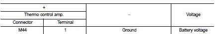
Is the inspection result normal? YES >> GO TO 3.
NO >> Repair harness or connector between thermo control amp. and fuse.
3.CHECK THERMO CONTROL AMP. GROUND CIRCUIT FOR OPEN
1. Turn ignition switch OFF.
2. Check continuity between thermo control amp. harness connector and ground.
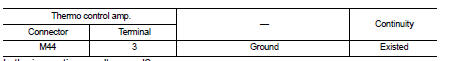
Is the inspection result normal? YES >> GO TO 4.
NO >> Repair harness or connector.
4.CHECK THERMO CONTROL AMP. SIGNAL
1. Turn ignition switch ON.
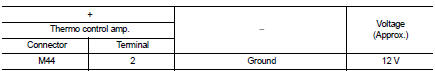
2. Check voltage between thermo control amp. harness connector and ground.
Is the inspection result normal? YES >> Replace thermo control amp. Refer to HAC-240, "Removal and Installation".
NO >> GO TO 5.
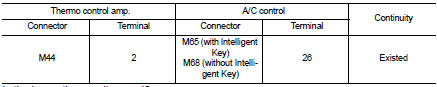
5.CHECK THERMO CONTROL AMP. SIGNAL CIRCUIT FOR OPEN
1. Turn ignition switch OFF.
2. Disconnect BCM connector.
3. Check continuity between thermo control amp. harness connector and BCM harness connector.
Is the inspection result normal? YES >> Replace BCM. Refer to BCS-93, "Removal and Installation" (with Intelligent Key) or BCS-161, "Removal and Installation" (without Intelligent Key).
NO >> Repair harness or connector.
 Blower fan on signal
Component Function Check
1.CHECK BLOWER FAN ON SIGNAL
With CONSULT-III
1. Turn ignition switch ON.
2. Select “AIR CONDITIONER” of “BCM” using CONSULT-III.
3. Select “FAN ON SIG” in “DATA MONITOR” ...
 A/C indicator
Diagnosis Procedure
1.CHECK SYMPTOM
Check symptom.
A/C indicator dose not turn ON>>GO TO 2.
A/C indicator dose not turn OFF>>GO TO 6.
2.CHECK FUSE
1. Turn ignition switch OFF.
...
Other materials:
Fuel gauge
The gauge1 indicates the approximate fuel level in the tank.
The gauge may move slightly during braking, turning, acceleration, or going up
or down hills.
Refill the fuel tank before the gauge registers 0 (empty). The low fuel
warning light illuminates when the
amount of fuel in the tank ...
Basic inspection
1.INSPECTION START
1. Check service records for any recent repairs that may indicate a related
malfunction, or a current need for
scheduled maintenance.
2. Open engine hood and check the following:
- Harness connectors for improper connections
- Wiring harness for improper connections, pinche ...
Component parts
Component Parts Location
1. Parking brake switch
2. Seat belt buckle switch (passenger
side)
3. Occupant detection unit
(Under the passenger seat cushion
pad)
4. ABS actuator and electric unit (control
unit)
Refer to BRC-97, "Component Parts
Location" (with ESP).
Refer to B ...
