Nissan Juke Service and Repair Manual : A/C indicator
Diagnosis Procedure
1.CHECK SYMPTOM
Check symptom.
A/C indicator dose not turn ON>>GO TO 2.
A/C indicator dose not turn OFF>>GO TO 6.
2.CHECK FUSE
1. Turn ignition switch OFF.
2. Check 10A fuse (No. 15, located in fuse block (J/B)].
NOTE
:
Refer to PG-22, "Fuse, Connector and Terminal Arrangement".
Is the inspection result normal? YES >> GO TO 3.
NO >> Replace the blown fuse after repairing the affected circuit if a fuse is blown.
3.CHECK A/C INDICATOR POWER SUPPLY
1. Turn ignition switch ON.
2. Check voltage between A/C control harness connector and ground.
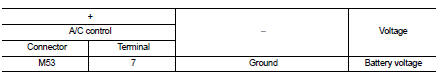
Is the inspection result normal? YES >> GO TO 4.
NO >> Repair harness or connector between A/C control and fuse.
4.CHECK A/C INDICATOR CIRCUIT
Check voltage between A/C control harness connector and ground.
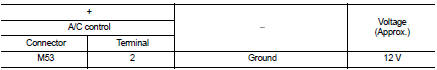
Is the inspection result normal? YES >> GO TO 5.
NO >> Replace A/C control. Refer to HAC-239, "Removal and Installation".
5.CHECK A/C INDICATOR CIRCUIT FOR OPEN
1. Turn ignition switch OFF.
2. Disconnect A/C control connector and BCM connector.
3. Check continuity between A/C control harness connector and BCM harness connecto
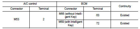
Is the inspection result normal? YES >> Replace BCM. Refer to BCS-93, "Removal and Installation" (with Intelligent Key) or BCS-161, "Removal and Installation" (without Intelligent Key).
NO >> Repair harness or connector.
6.CHECK A/C INDICATOR CIRCUIT FOR SHORT
1. Turn ignition switch OFF.
2. Disconnect A/C control connector and BCM connector.
3. Check continuity between A/C control harness connector and ground.
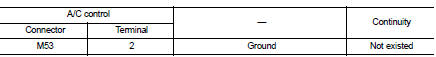
Is the inspection result normal? YES >> Replace BCM. Refer to BCS-93, "Removal and Installation" (with Intelligent Key) or BCS-161, "Removal and Installation" (without Intelligent Key).
NO >> Repair harness or connector
 Thermo control amplifier
Component Function Check
1.CHECK A/C ON SIGNAL
With CONSULT-III
1. Turn ignition switch ON.
2. Select “AIR CONDITIONER” of “BCM” using CONSULT-III.
3. Select “THERMO AMP” in “DATA MONITOR” mode, ...
 Blower motor
Diagnosis Procedure
1.CHECK SYMPTOM
Check symptom (A or B).
Which symptom is detected?
A >>GO TO 2.
B >>GO TO 7.
2.CHECK FUSE
1. Turn ignition switch OFF.
2. Check 15A fuses ...
Other materials:
Compressor dose dot operate
Description
SYMPTOM
Compressor dose not operate.
Diagnosis Procedure
NOTE:
• Perform self-diagnosis with CONSULT-III before performing symptom diagnosis.
If any malfunction result or
DTC is detected, perform the corresponding diagnosis.
• Check that refrigerant is enclosed in cooler cycle n ...
P0500 VSS
Description
The vehicle speed signal is sent to the combination meter from the “ABS
actuator and electric unit (control
unit)” by CAN communication line. The combination meter then sends a signal to
the ECM by CAN communication
line.
DTC Logic
DTC DETECTION LOGIC
NOTE:
• If DTC P0500 is d ...
Front disc brake
Brake pad : Inspection and Adjustment
INSPECTION
Check brake pad wear thickness from an inspection hole on cylinder
body. Check using a scale if necessary.
Wear thickness : Refer to BR-71, "Front Disc Brake".
ADJUSTMENT
Burnish contact surfaces between disc rotor and brake pads acc ...
